Apparatus and method for layer jump braking control in an optical drive
- Summary
- Abstract
- Description
- Claims
- Application Information
AI Technical Summary
Benefits of technology
Problems solved by technology
Method used
Image
Examples
Embodiment Construction
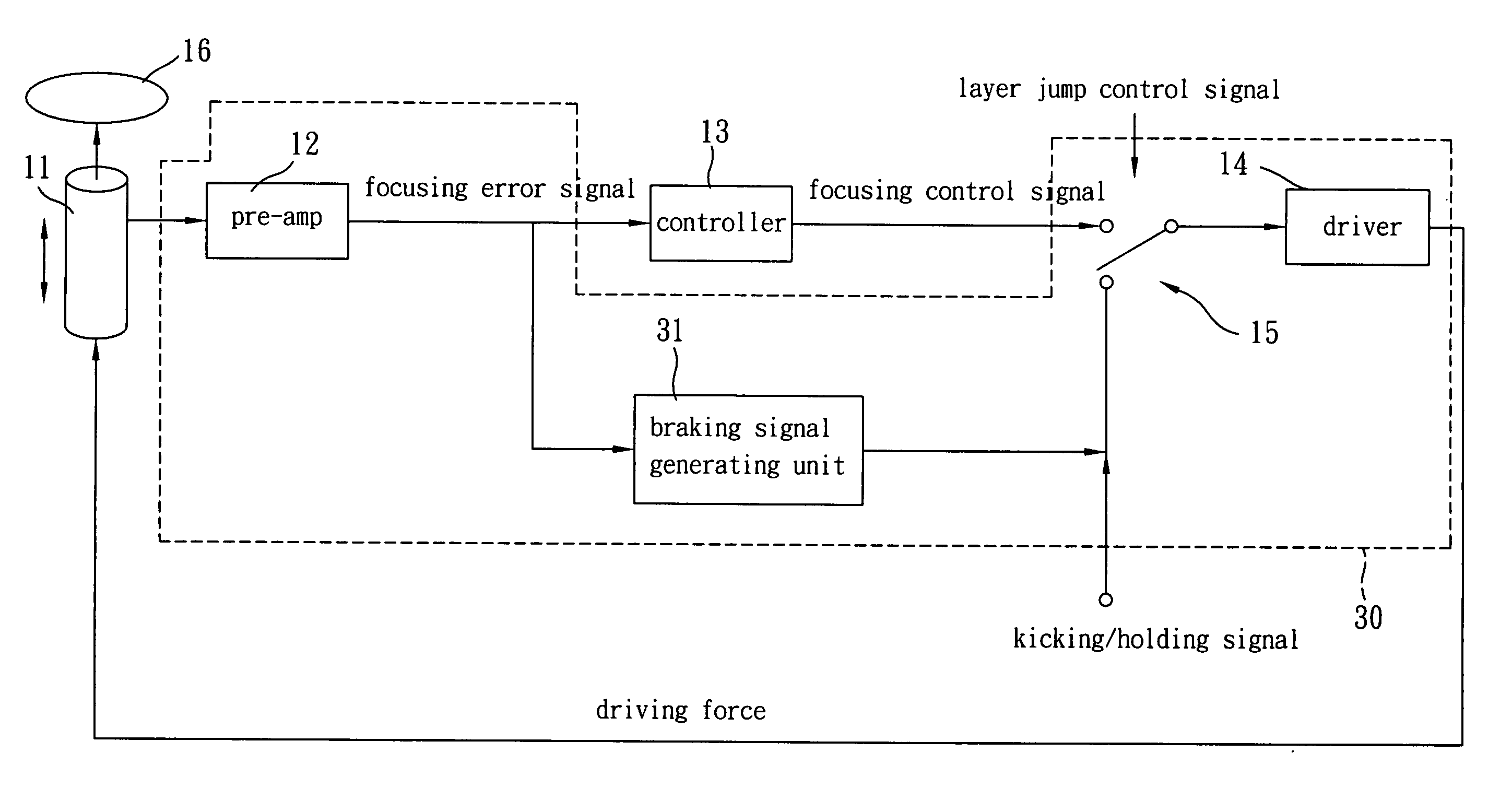
[0021]FIG. 3 is a block diagram of a preferred embodiment of the apparatus for layer jump braking control according to the present invention. In FIG. 3, the apparatus 30 is set in an optical disk drive, e.g. DVD drive. The optical disk drive includes a pick up head 11, which moves vertically against a disk 16 (e.g. DVD disk) with at least two layers to perform a layer jump process that includes a layer jump braking process. The apparatus 30 includes a pre-amp 12, a braking signal generating unit 31, a driver 14, and a switch 15. The pre-amp 12 is coupled to the pick up head 11, and generates a focusing error signal. The braking signal generating unit 31 receives the focusing error signal, and generates a corresponding non-fixed braking signal. The driver 14 is coupled to the braking signal generating unit 31 via the switch 15, and according to the non-fixed braking signal, generates a corresponding driving force for controlling the pick up head 11 to perform the layer jump braking p...
PUM
 Abstract
Description
Claims
Application Information
 - R&D
- Intellectual Property
- Life Sciences
- Materials
- Tech Scout
- Unparalleled Data Quality
- Higher Quality Content
- 60% Fewer Hallucinations
Browse by: Latest US Patents, China's latest patents, Technical Efficacy Thesaurus, Application Domain, Technology Topic, Popular Technical Reports.
© 2025 PatSnap. All rights reserved.Legal|Privacy policy|Modern Slavery Act Transparency Statement|Sitemap|About US| Contact US: help@patsnap.com


