
Mobile communication network using mobile station with relay-function and method for rewarding relay activities of mobile station

a mobile communication network and relay technology, applied in the field of mobile communications networks, can solve the problems of inconvenient user reconnection, restricted user mobility, network reconnection is not without problems, etc., and achieve the effects of increasing network access, extending call-time of said first mobile terminal, and increasing network access

Inactive Publication Date: 2005-10-13
HITACHI LTD
View PDF5 Cites 55 Cited by
  • Summary
  • Abstract
  • Description
  • Claims
  • Application Information

AI Technical Summary

Benefits of technology

[0010] This has the advantage that use of the second mobile as a relay may be monitored and rewarded.
[0026] According to the present invention there is provided a method, in a mobile communications network, of rewarding a first mobile terminal for relaying signals between a second mobile terminal and either a third mobile terminal or a fixed station, the method comprising extending call-time of said first mobile terminal.
[0027] According to the present invention there is provided a method of operating a mobile communications network including a first mobile terminal for relaying signals between a second mobile terminal and either a third mobile terminal or a fixed station, the method comprising rewarding the first mobile terminal for relaying said signals with increased network access.
[0028] The rewarding of the first mobile terminal with increased network access may comprise increasing call-time or data volume available to the first mobile terminal.

Problems solved by technology

Fixed communication networks tend to restrict mobility of the users.
This is inconvenient for the user since network connection is temporality lost.
Moreover, network reconnection is not without its problems, particularly as it requires a connection point at the new location.
However, access can be restricted by the connections provided by base stations.
For example, at a physical level, a radio link between the terminal and the base station may be of poor quality.
Alternatively, at a resource level, the base station may not be able to provide sufficient channels to mobile terminals requiring service.
However, this solution is expensive and relies upon being able to find suitable sites for the additional base stations.

Method used


Image

  • Mobile communication network using mobile station with relay-function and method for rewarding relay activities of mobile station
  • Mobile communication network using mobile station with relay-function and method for rewarding relay activities of mobile station
  • Mobile communication network using mobile station with relay-function and method for rewarding relay activities of mobile station

Examples


Embodiment Construction

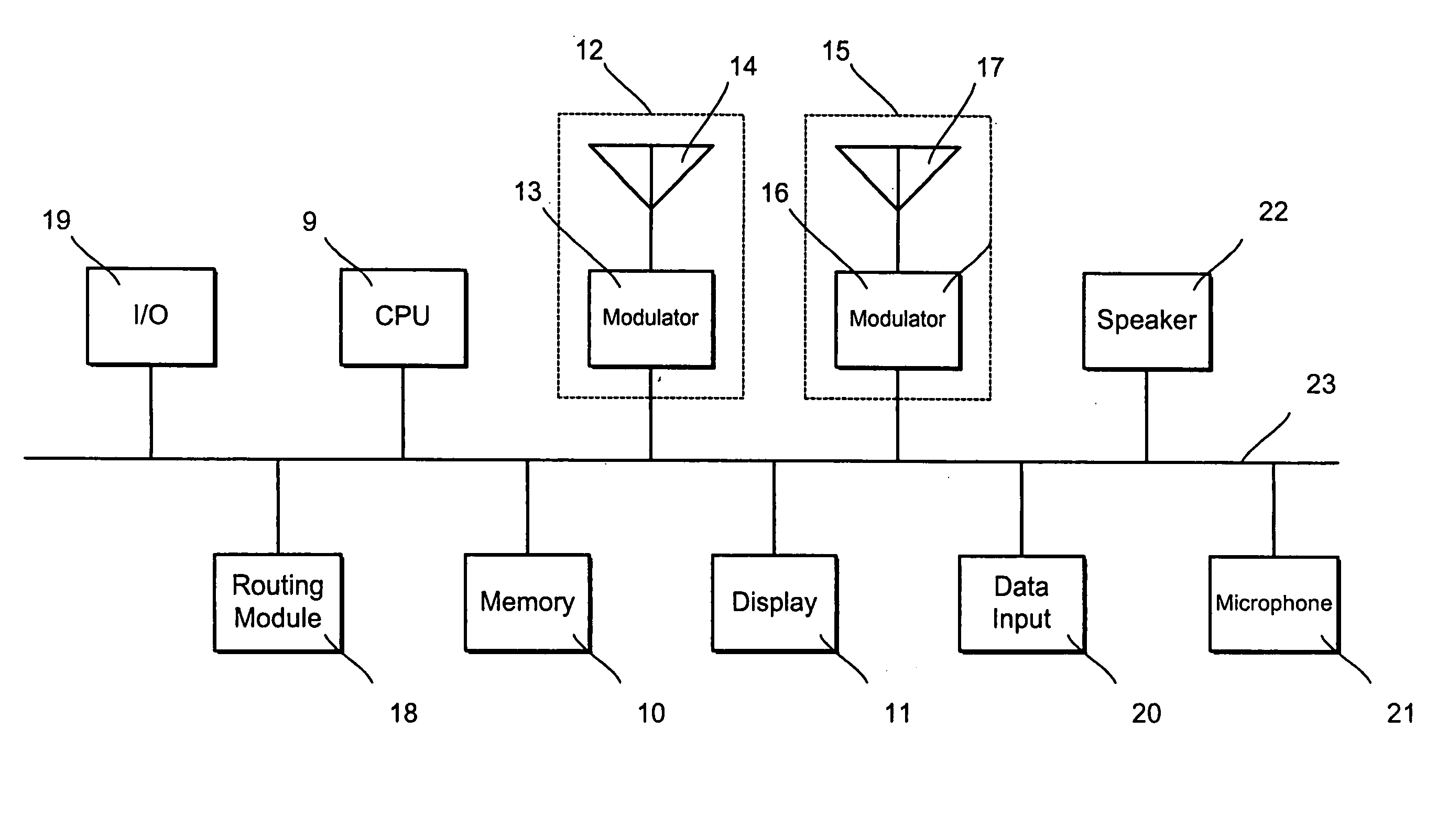
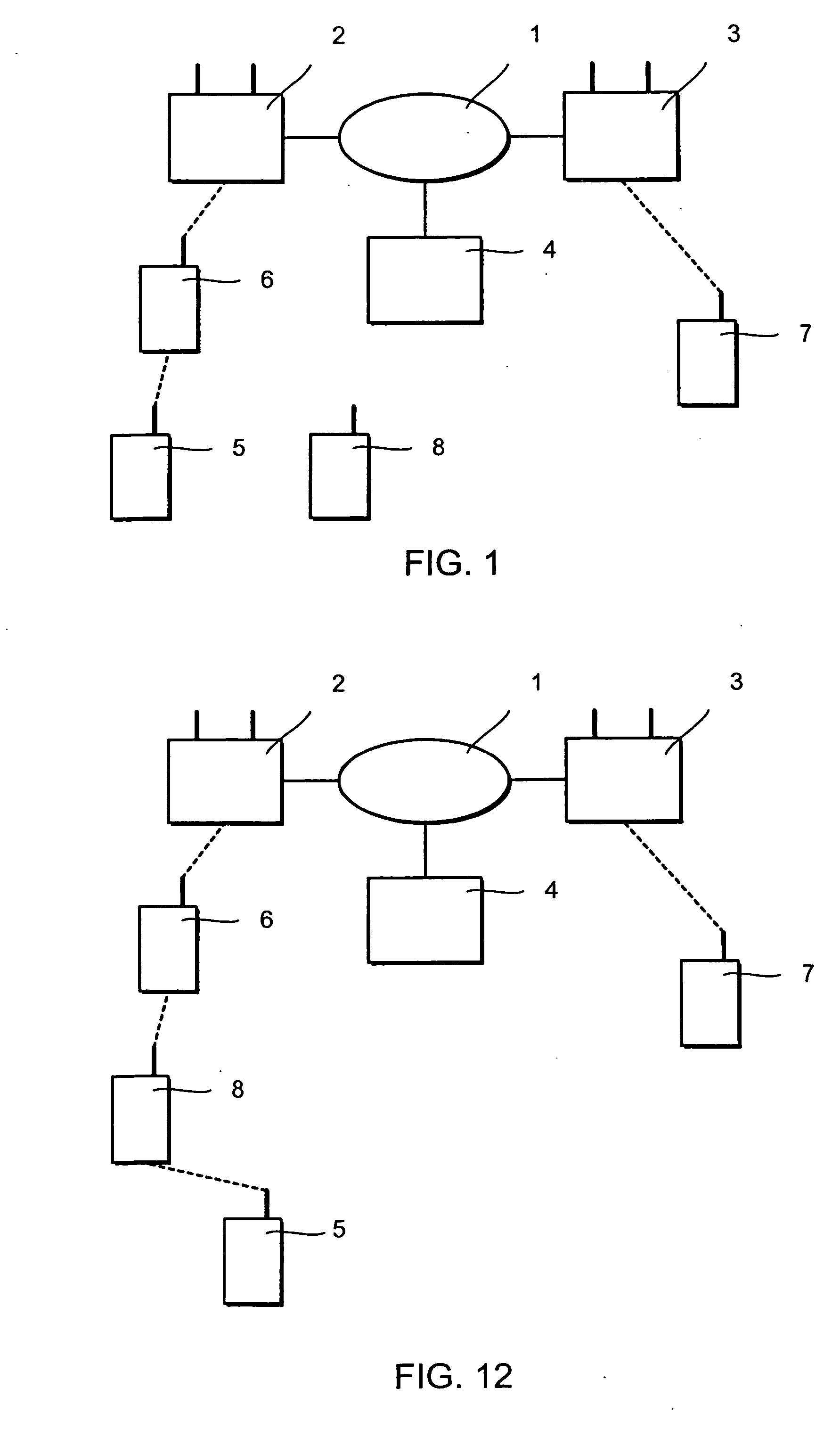
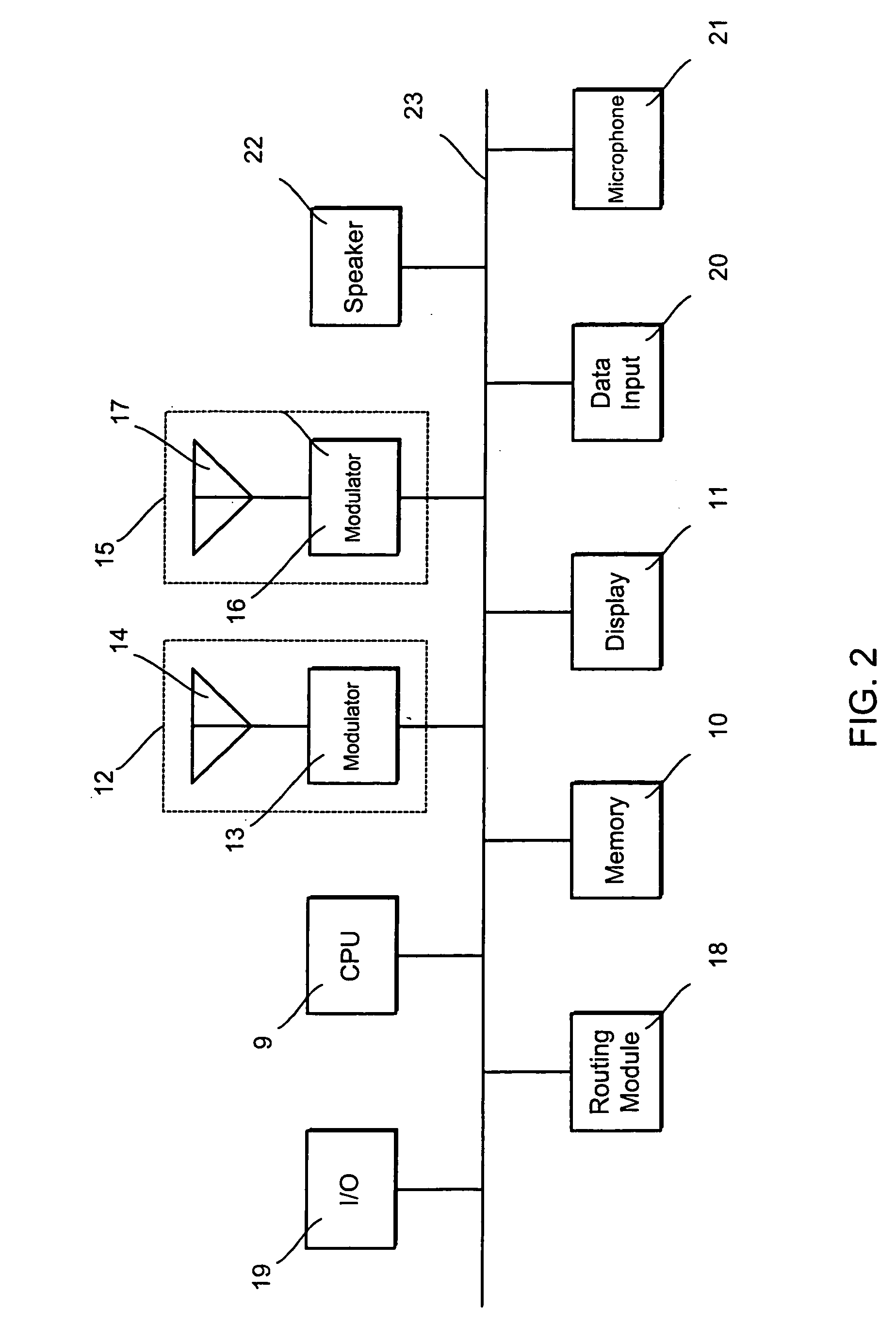
[0043] Referring to FIG. 1, in a first embodiment of the present invention, a mobile communications network 1 includes first and second base stations 2, 3. In this example, the network 1 is a public land mobile network (PLMN), such as a GSM network. The network 1 includes a server 4 for logging network use and will be described in more detail later.

[0044] A description of a GSM network can be found in “The GSM System for Mobile Communications” by Michel Mouly and Marie-Bernadette Pautet (Cell & Sys, Palaiseau, 1992).

[0045] First, second, third and fourth mobile terminals 5, 6, 7, 8 are suitable for use with the network 1. Each terminal 5, 6, 7, 8 can be used to communicate with other mobile terminals or, via an additional fixed communications network (not shown), with fixed terminals (not shown). For example, the fixed communications network can be a public switched telephone network.

[0046] A problem can sometimes arise that the first mobile terminal 5 is temporarily unable to us...


PUM


Abstract

A GSM network (1) includes a base station (2). A first mobile terminal (5) is outside a region of coverage. Using Bluetooth network, a second terminal (6) relays signals between the first terminal and the base station. The second terminal is awarded credit for relaying the signals.

Description

FIELD OF THE INVENTION [0001] The present invention relates to a mobile communications network. BACKGROUND ART [0002] A fixed communication network generally allows data or voice to be communicated between fixed terminals. An example of such a network is a public switched telephone network (PSTN) in which subscribers communicate using fixed telephone sets. Other examples include wired local-area networks (LANs) and wide-area networks (WANs), which are mainly used for transmission of data between computers. Fixed communication networks tend to restrict mobility of the users. If the user moves, they often have little choice but to disconnect their terminal from the network and reconnect at a different location. This is inconvenient for the user since network connection is temporality lost. Moreover, network reconnection is not without its problems, particularly as it requires a connection point at the new location. [0003] A mobile communication network helps to overcome these problems...

Claims


Application Information

Patent Timeline
Patent Type & Authority Applications(United States)
IPC IPC(8): H04B7/26H04L12/701H04W4/24H04W8/22H04W40/10H04W88/02H04W88/04H04W88/08
CPCH04B7/2606H04L45/00H04W4/24H04W88/08H04W40/10H04W88/02H04W88/04H04W8/22Y02D30/70
Inventor TAKATANI, YUKIHIRONONAKA, NAOMICHIHAYASHI, MASATO
Owner HITACHI LTD
Learn More