Adjustable-angle spinal fixation element

Active Publication Date: 2005-10-13
MEDOS INT SARL
View PDF45 Cites 176 Cited by
  • Summary
  • Abstract
  • Description
  • Claims
  • Application Information

AI Technical Summary

Benefits of technology

[0012] In yet another embodiment of the present invention, the connecting feature on each of the first and second elongate members can be slidably coupled to one another. More preferably, the connecting feature on each of the first and second elongate members is a substantially curved terminal portion, and the terminal portion are complementary for slidably mat

Problems solved by technology

Although each region of the spine presents unique clinical challenges, posterior fixation of the cervical spine is particularly challenging.
The anatomy of the cervical spine makes it a technically challenging area to instrument.
It is often the case that the predetermined contour of a fixation rod does not exactly fit the contour of the implant

Method used


Image

  • Adjustable-angle spinal fixation element
  • Adjustable-angle spinal fixation element
  • Adjustable-angle spinal fixation element

Examples


Example

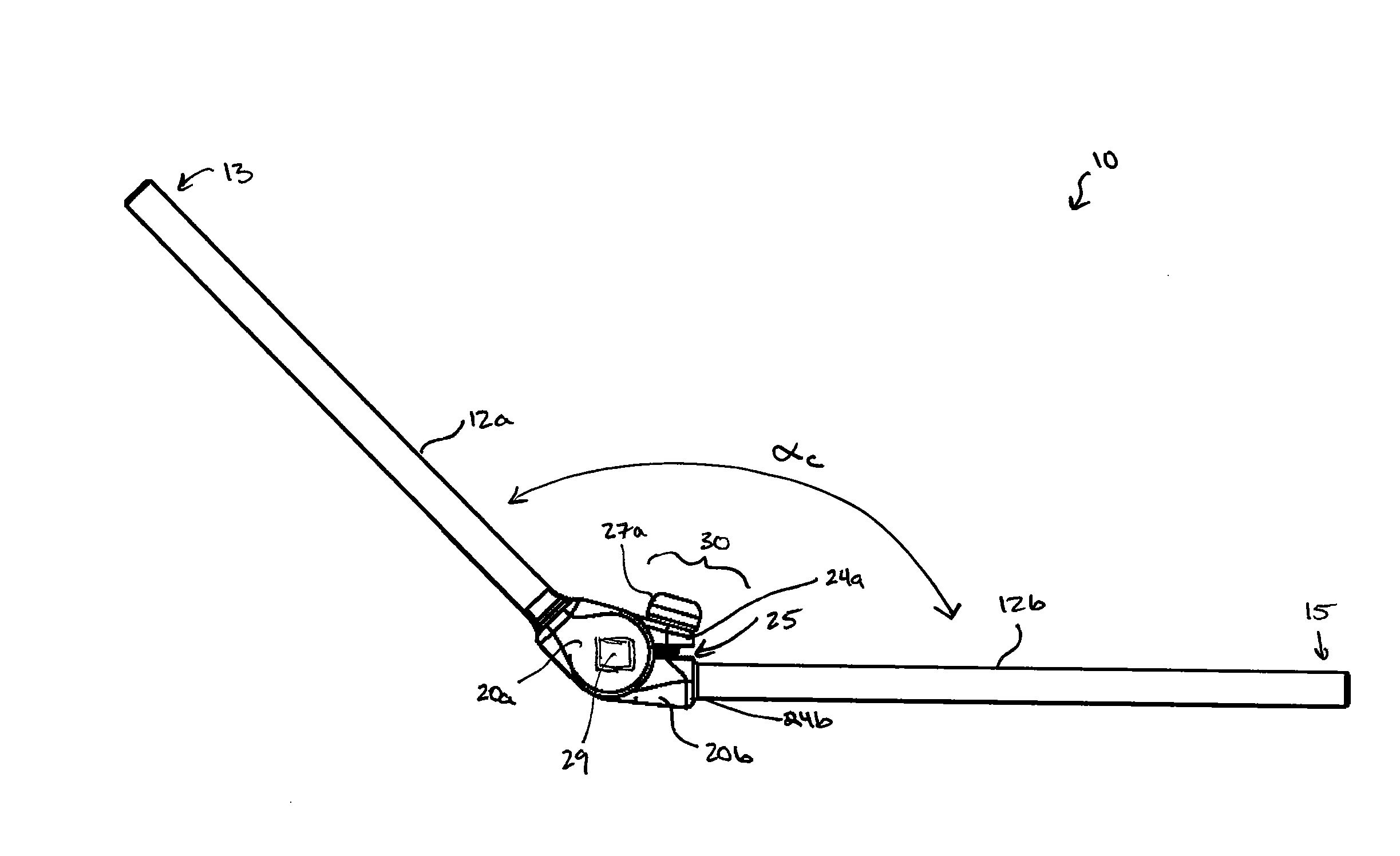
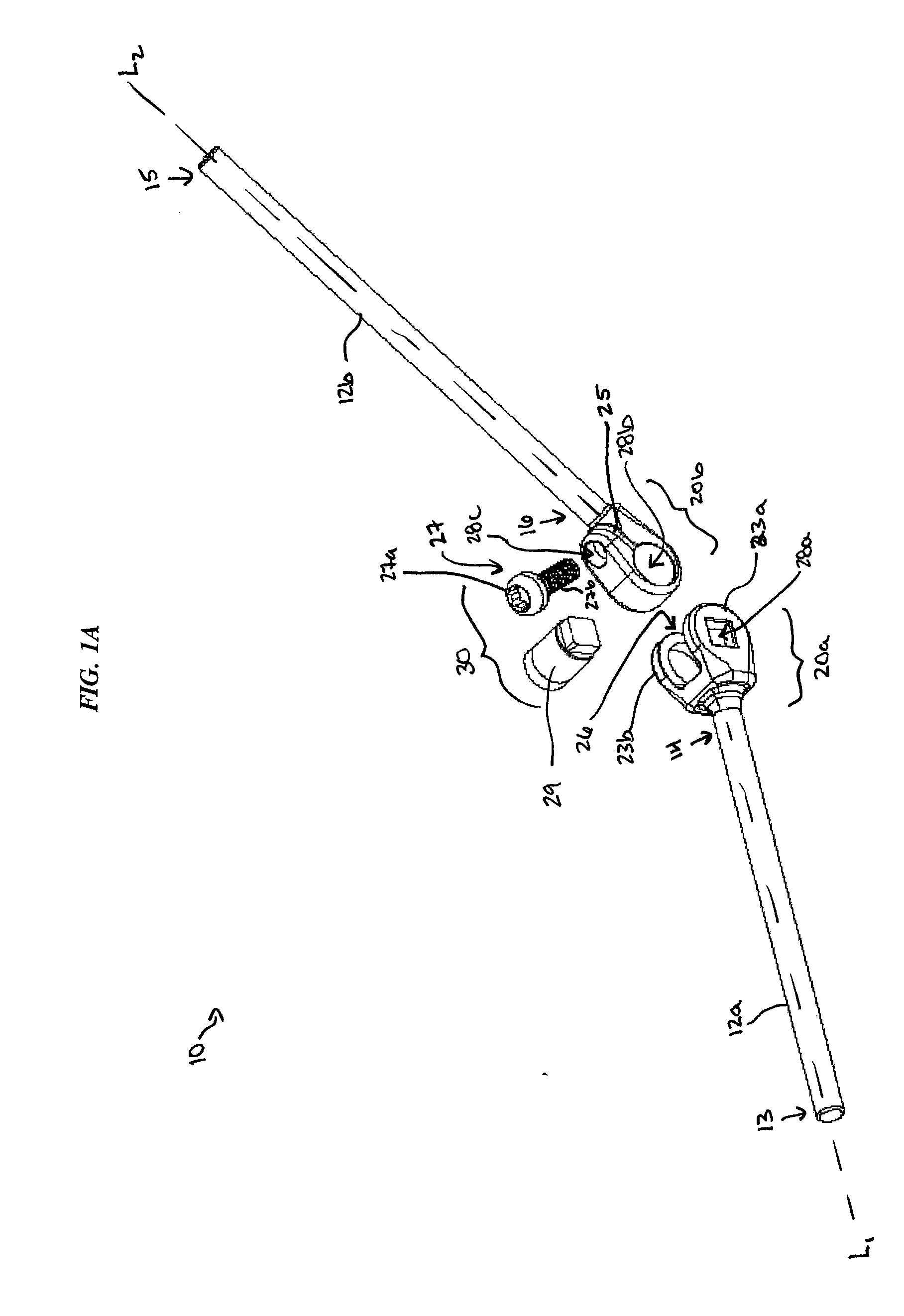
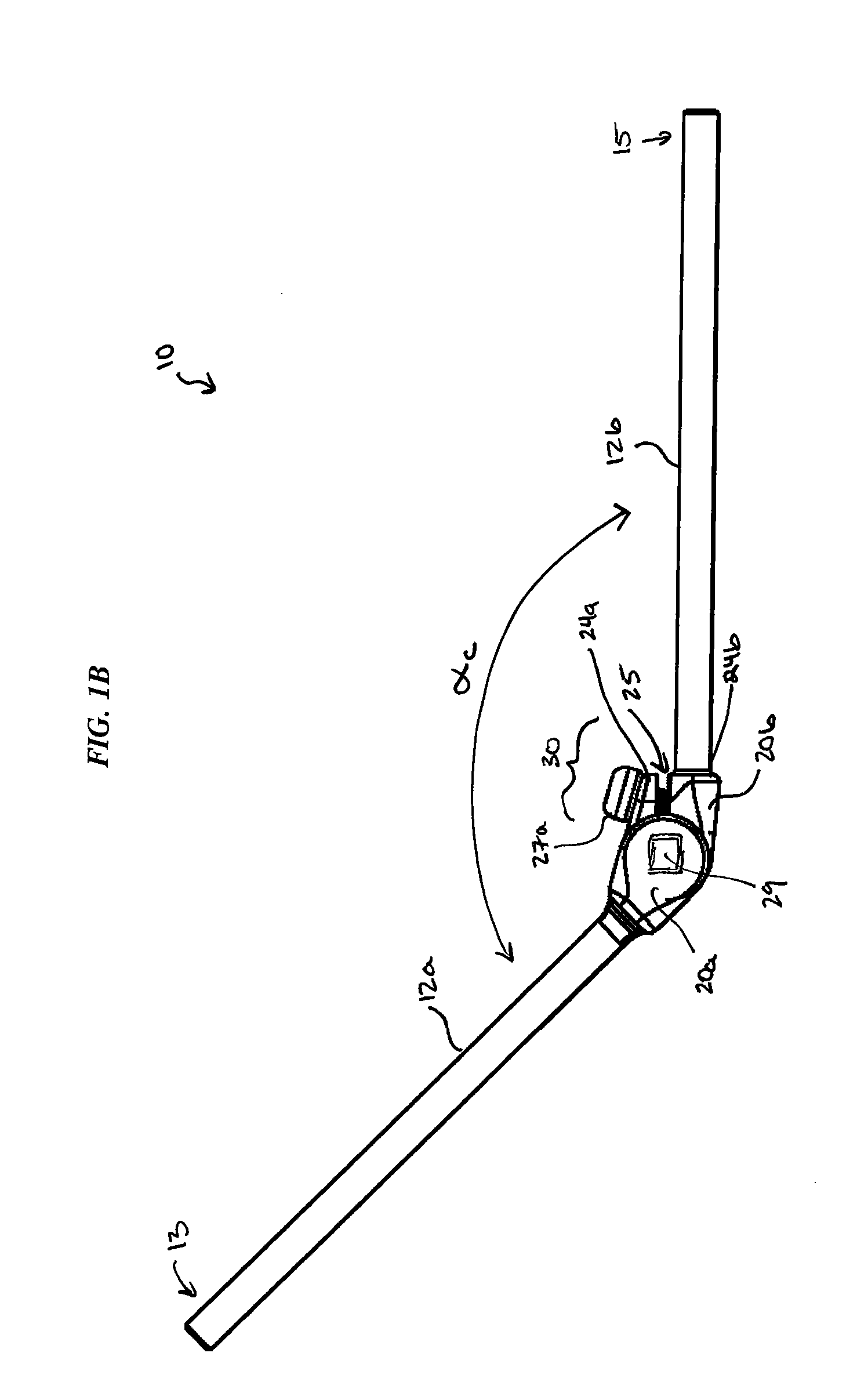
[0027] The present invention provides various angularly-adjustable spinal fixation devices, each of which generally includes first and second elongate members 12a, 12b, a connecting feature 20 formed on a terminal end of each of the first and second elongate members 12a, 12b, and a locking mechanism 30 that is adapted to lock the first and second elongate members 12a, 12b in a fixed position relative to one another. The elongate members 12a, 12b are preferably spinal rods and / or plates that are used, for example, in the stabilization of the spine following trauma, tumor, or degenerative pathologies. Among many other advantages, the devices are particularly useful to allow a spinal rod to be positioned and locked in a desired angular orientation without the need to reshape the rod, and without requiring the point of adjustment to be attached to the spine of a patient.

[0028]FIGS. 1A-1B illustrate one exemplary embodiment of a spinal fixation device 10 having first and second elongate...


PUM


Abstract

A spinal fixation device is provided having first and second elongate members that are angularly adjustable relative to one another. Each elongate member can include a connecting feature formed on a terminal end thereof, and each connecting feature can be coupled to one another to allow angular movement of the first and second elongate members. The device can also include a locking mechanism that is adapted to couple to the connecting feature on each of the first and second elongate members to lock the elongate members in a fixed position relative to one another.

Description

FIELD OF THE INVENTION [0001] The present application relates to devices for use in spinal surgery, and in particular to spinal fixation devices having an adjustable angle. BACKGROUND OF THE INVENTION [0002] Stabilization of the spine is often required following trauma, tumor, or degenerative pathologies. Although each region of the spine presents unique clinical challenges, posterior fixation of the cervical spine is particularly challenging. The anatomy of the cervical spine makes it a technically challenging area to instrument. Specifically, several vital neural and vascular structures, including the vertebral arteries, nerve roots, and spinal cord, must be avoided during surgery. [0003] Current methods of posterior cervical stabilization include the use of an occipital spinal plate and a transition rod for fixation of the cervico-thoracic junction. Such devices typically include a spinal fixation element, such as a relatively rigid fixation rod, that is coupled to adjacent verte...

Claims


Application Information

Patent Timeline
IPC IPC(8): A61B17/56A61B17/58A61B17/70
CPCA61B17/7013A61B17/7023A61B17/7055A61B17/705A61B17/7002A61B17/7052A61B17/7059
Inventor BOOMER, MARK C.JONES, BRYAN S.MURPHY, RAYMOND F.
Owner MEDOS INT SARL
Why Eureka
Try Eureka