Intravascular balloon occlusion device and method for using the same

a technology of occlusion device and balloon, which is applied in the field of intravascular balloon occlusion device, can solve the problems of increasing the patient's blood loss during the surgical procedure, flooding the surgical field with blood, etc., and achieves the effect of keeping the surgical field clear

Inactive Publication Date: 2005-10-13
MEDTRONIC INC
View PDF18 Cites 0 Cited by
  • Summary
  • Abstract
  • Description
  • Claims
  • Application Information

AI Technical Summary

Benefits of technology

[0010] In an alternative embodiment, an irrigation aperture is provided in the body of the device proximally of the first and second inflatable members. An irrigation lumen extends to the body from the irrigation aperture to the proximal end of the body, preferably the connector. With this structure, the user can irrigate the area proximally of the first inflation member thereby keeping the surgical field clear.

Problems solved by technology

A problem with this procedure is that it is desirable to continue blood flow through the aorta at all times in order to continue blood flow throughout the body.
However, if the surgeon were to punch a hole in the aorta while the blood was flowing therethrough, some blood would flow out the hole, thereby flooding the surgical field with blood and increasing the patient's blood loss during the surgical procedure.
One problem with the prior art coronary artery bypass graft procedures and instruments used therefore is providing means for sealing the aorta so that the hole punches and grafts can be formed therein while continuing the flow of blood through the aorta.

Method used


Image

  • Intravascular balloon occlusion device and method for using the same
  • Intravascular balloon occlusion device and method for using the same
  • Intravascular balloon occlusion device and method for using the same

Examples


Embodiment Construction

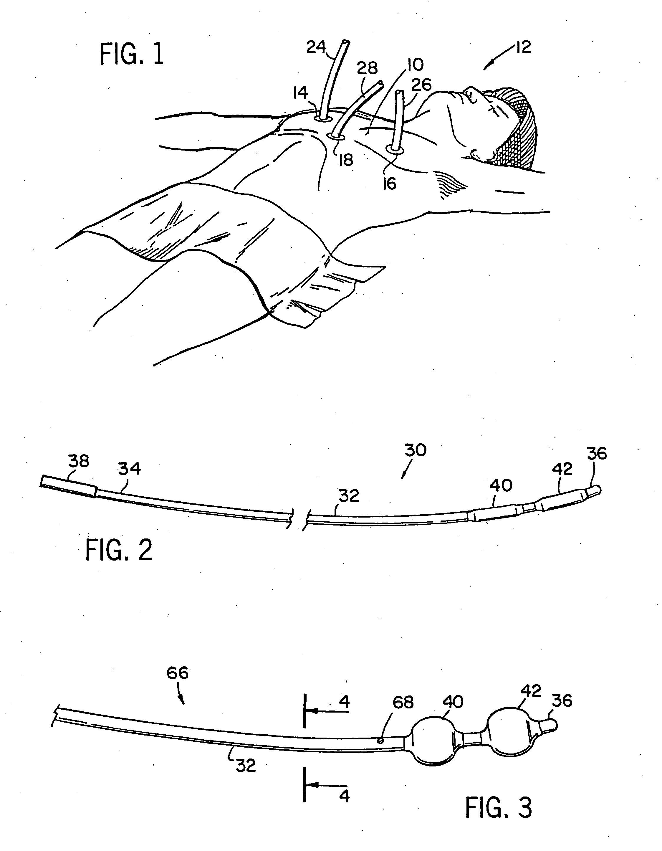
[0023] In minimally invasive surgical procedures, such as that shown in FIG. 1, multiple small incisions are made in the chest wall for receipt of surgical instruments. For example, two relatively small incisions are made in the chest wall 10 of a patient 12 at different, small interstitial rib positions, while a third incision is made just below the sternum. A first trocar 14 is inserted into the first incision at one of the interstices while a second trocar 16 is inserted into the second incision at another of the interstices. Preferably, the first and second incisions are made on opposite sides of the sternum. A third trocar 18 is inserted into the incision just below the sternum. Each trocar is conventional in nature and has a central aperture (not shown) formed therein. The central aperture is adapted to receive one of a variety of surgical instruments such as an endoscope, electro-cautery pen and the like for performing the minimally invasive surgical procedures. First, second...


PUM


Abstract

An intravascular balloon occlusion device according to the invention is shown. The device is ideally suited for use in a coronary artery bypass graft procedure. The device includes a body having at least one selectively inflated balloon provided on the distal end thereof. Preferably, the body is a closed end body so that fluid can only flow from the proximal end of the body into the balloon. In use, the distal end of the body and the balloon are inserted into an aperture provided in the aorta. The balloon is inflated and then the device is retracted until the balloon seats against the incision or aperture in the aorta, thereby effectively sealing the aperture from the blood flow through the aorta, but not occluding blood flow through the body of the aorta itself Next, the graft vessel is telescopically positioned on the occlusion device and mounted to the aorta Once the vessel is secured thereto, the balloon is deflated and then the occlusion device is retracted from both the aorta and the graft vessel. Finally, the second end of the graft vessel is mounted to the appropriate coronary artery.

Description

BACKGROUND OF THE INVENTION [0001] 1. Field of the Invention [0002] This invention relates to an intravascular balloon occlusion device, a portion of which is adapted to be positioned inside a vessel during surgical procedures and, more particularly, to an aortic balloon occlusion device wherein the balloon is adapted to seal portions of the aorta while blood flows therethrough. [0003] 2. Description of the Related Art [0004] A current trend in coronary bypass surgery is to utilize a minimally invasive surgical procedure. In such a procedure, there is no need to open the chest through a conventional open heart surgical procedure. Rather, multiple access points are created for the receipt of the necessary surgical tools. This procedure has the distinct advantages of minimizing trauma to the tissue surrounding the heart and chest cavity. [0005] In performing a coronary bypass, one end of a bypass vein is attached to the ascending aorta while the other end of the bypass artery is attac...

Claims


Application Information

Patent Timeline
Patent Type & Authority Applications(United States)
IPC IPC(8): A61B17/12A61B17/32A61F2/958A61M29/00
CPCA61B17/12136A61M2025/1052A61M25/1011A61B17/32053
Inventor JONKMAN, KENNETH R.ROM, PAUL F.
Owner MEDTRONIC INC
Why Eureka
Try Eureka