Dust collecting apparatus for a vacuum cleaner

Inactive Publication Date: 2005-10-20
SAMSUNG GWANGJU ELECTRONICS CO LTD
View PDF9 Cites 68 Cited by
  • Summary
  • Abstract
  • Description
  • Claims
  • Application Information

AI Technical Summary

Benefits of technology

[0012] The present invention has been conceived to solve the above-mentioned problems occurring in the prior art vacuum cleaners, and an aspect of the present invent

Problems solved by technology

These types of cyclone vacuum cleaner dust collecting apparatus are used instead of a dust bag, which have a relatively short life span.
Therefore, the cyclone

Method used


Image

  • Dust collecting apparatus for a vacuum cleaner
  • Dust collecting apparatus for a vacuum cleaner
  • Dust collecting apparatus for a vacuum cleaner

Examples


Example

[0030] Certain preferred embodiments of the present invention will be described in greater detail with reference to the accompanying drawings.

[0031] In the following description, the same drawing identification reference numerals are used to designate the same elements throughout the different drawing figures. The disclosure below is intended as merely a detailed construction and description of the elements and is provided to assist in a comprehensive understanding of the invention. Thus, it is apparent that the present invention can be carried out without some or all of these disclosed conventional parts. Also, well-known functions or constructions are not described in detail, since they would obscure the invention in unnecessary detail.

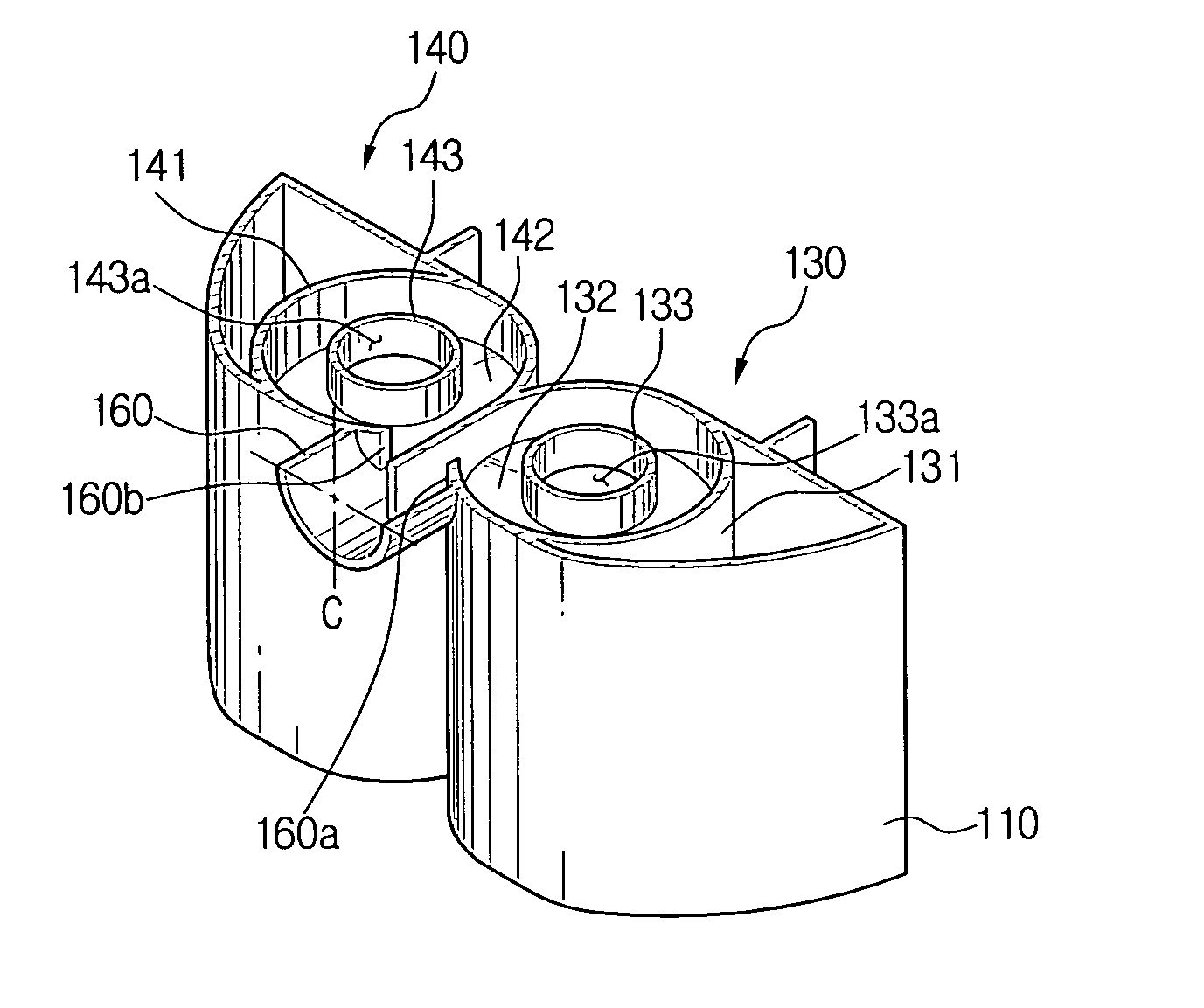
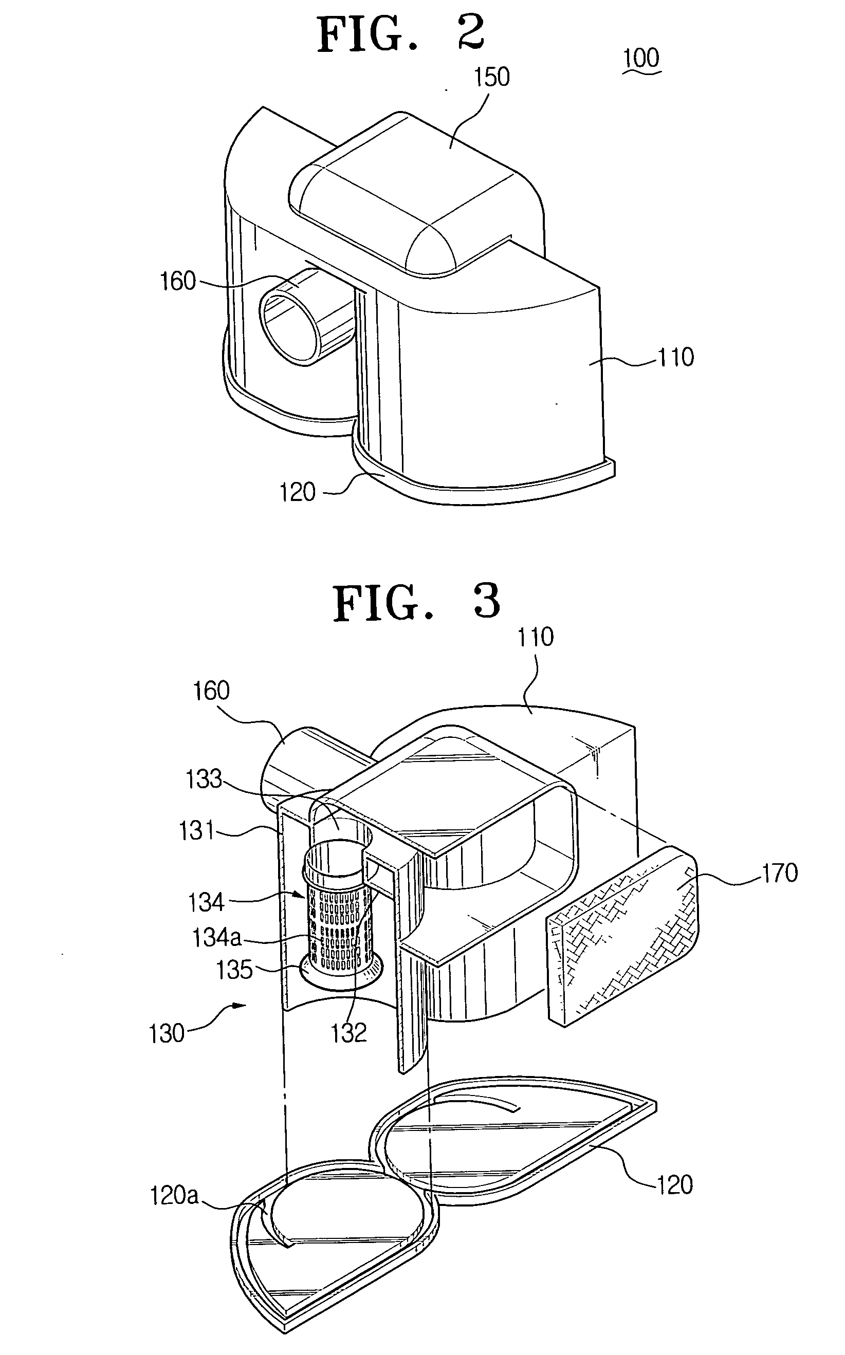
[0032] As shown in FIGS. 2 through 6, a dust collecting apparatus for a vacuum cleaner 100 according to an embodiment of the present invention comprises a casing 110, a lower cover 120, first and second cyclone dust collecting parts 130 and 140, a...


PUM

PropertyMeasurementUnit
Forceaaaaaaaaaa
Sizeaaaaaaaaaa
Areaaaaaaaaaaa

Abstract

A dust collecting apparatus for a vacuum cleaner has a first cyclone dust collecting part and a second cyclone dust collecting part that are arranged substantially parallel with respect to an air inflow opening of a vacuum cleaner main body, and may be mirror images of each other. The first cyclone dust collecting part comprises a first suction opening and a first discharge opening, and the second cyclone dust collecting part comprises a second suction opening and a second discharge opening. The first and second suction openings are connected with the air inflow opening of the vacuum cleaner main body, and the first and second discharge openings are connected with a vacuum suction chamber of the vacuum cleaner main body. Accordingly, a dust collecting apparatus for a vacuum cleaner can be realized, having an advanced suction capability and dust separation capability.

Description

CROSS-REFERENCE TO RELATED APPLICATIONS [0001] This application claims the benefit of Korean Patent Application No. 2004-26133 filed on Apr. 16, 2004, in the Korean Intellectual Property Office, the disclosure of which is incorporated herein by reference in its entirety. BACKGROUND OF THE INVENTION [0002] 1. Field of the Invention [0003] The present invention relates generally to a vacuum cleaner and more particularly, to a dust collecting apparatus for a vacuum cleaner for filtering air drawn into the vacuum cleaner to separate dust entrained therein. [0004] 2. Description of the Related Art [0005] Generally, a vacuum cleaner draws in external air by use of a suction force generated at a suction motor to collect dust in a collecting means, such as a dust bag. Various types of vacuum cleaners, such as an upright type, a canister type and a stick type are available. [0006] Recently, vacuum cleaners using a cyclone duct collecting apparatus having a semi-permanent life span are experi...

Claims


Application Information

Patent Timeline
IPC IPC(8): A47L9/16A47L9/00B01D45/12B01D45/16B04C5/04B04C5/28B04C9/00
CPCA47L9/1641A47L9/1683B04C5/28B04C5/04B01D45/16Y10S55/03A47L9/16
Inventor OH, JANG-KEUNHAN, JUNG-GYUN
Owner SAMSUNG GWANGJU ELECTRONICS CO LTD
Why Eureka
Try Eureka