Compression cooling system and method for evaluating operation thereof

a cooling system and compression technology, applied in the field of compression conditioning systems, can solve the problems of affecting the seal nature of the system and affecting the cooling effect of the system, and achieve the effect of reducing the risk of vaporization

Inactive Publication Date: 2005-10-20
LENNOX MFG
View PDF4 Cites 87 Cited by
  • Summary
  • Abstract
  • Description
  • Claims
  • Application Information

AI Technical Summary

Benefits of technology

[0017] It is yet a further object of the present invention to provide a compression cooling system and method for evaluating operat

Problems solved by technology

This connection of pressure gauges necessarily involves breaching the cooling system, which involves a risk that the sealed nature of the system may be compromised and refrige

Method used


Image

  • Compression cooling system and method for evaluating operation thereof
  • Compression cooling system and method for evaluating operation thereof
  • Compression cooling system and method for evaluating operation thereof

Examples


Embodiment Construction

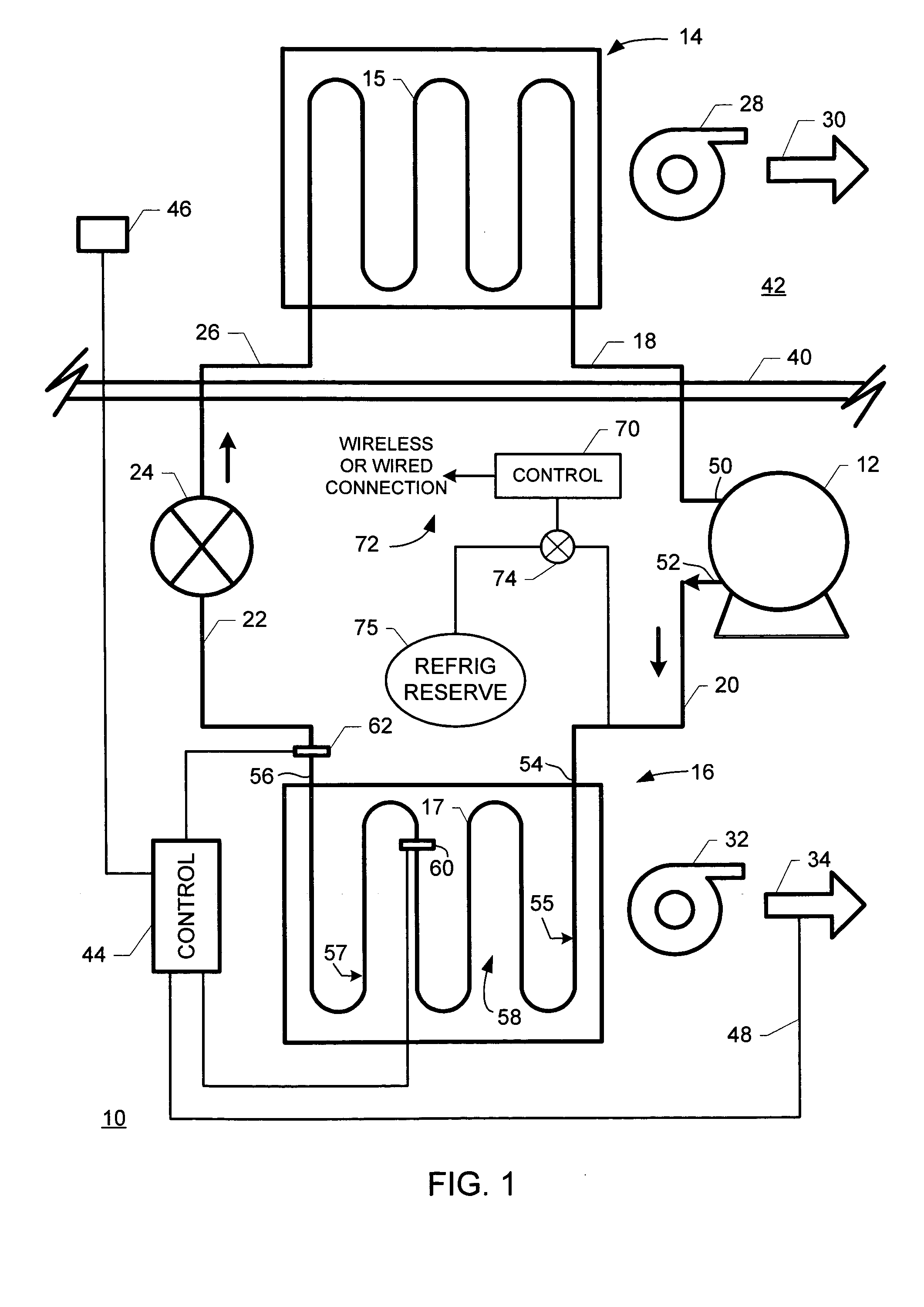
[0021]FIG. 1 is a schematic diagram illustrating a compression cooling system configured according to the present invention. In FIG. 1, a cooling system 10 includes a compressor 12, an evaporator 14 and a condenser 16. A fluid line 18 fluidly couples evaporator 14 with compressor 12. A fluid line 20 fluidly couples compressor 12 with condenser 16. A fluid line 22 fluidly couples condenser 16 with an expansion valve 24. A fluid line 26 fluidly couples expansion valve 24 with evaporator 14. By “fluidly couples” it is meant that fluid flows substantially freely within fluid lines 18, 20, 22, 26 to transport refrigerant (not shown separately in FIG. 1) among evaporator 14, condenser 112, condenser 16 and expansion valve 24. A blower fan 28 draws air across evaporator 14 generally in the direction indicated by arrow 30. A blower fan 32 draws air across condenser 16 generally in the direction indicated by arrow 34.

[0022] A building wall 40 bounds a building interior space 42 that is cool...


PUM


Abstract

A method for evaluating operation of a compression cooling system includes the steps of: (a) in no particular order: (1) measuring a first temperature of the refrigerant in a saturated state; and (2) measuring a second temperature of the refrigerant in a liquid state; and (b) calculating a difference between the first temperature and the second temperature to determine the extant amount of subcooling to which the refrigerant is subjected.

Description

BACKGROUND OF THE INVENTION [0001] The present invention is directed to compression conditioning systems, and especially to a vapor compression conditioning system, such as a heat pump or air conditioner, that does not require breaching the system to evaluate operation of the system, such as for evaluating state of charge of refrigerant in the system. [0002] Proper charge of refrigerant is a crucial requirement for maintaining efficient operation of a compression cooling system. Servicemen visit cooling systems on-site in order to check refrigerant level and to refill or recharge systems that are found to have a low refrigerant charge. Typical measurements performed by a service representative in checking a system involve hauling heavy, unwieldy pressure gauges to the condenser unit of the system (usually located outside the cooled premises, such as on a roof or in a yard). The pressure gauges are hooked up to the refrigerant line of the cooling system so that pressure in the refrig...

Claims


Application Information

Patent Timeline
IPC IPC(8): F25B45/00F25B49/00F25D17/02
CPCF25B45/00F25B49/005F25B2700/21163F25B2600/07F25B2700/2116F25B2500/19
Inventor HREJSA, PETER BRIANOLSEN, MARK WILLIAM
Owner LENNOX MFG
Why Eureka
Try Eureka