Eureka AIR delivers breakthrough ideas for toughest innovation challenges, trusted by R&D personnel around the world.

Arrangement for generating vortexes

a technology of vortexes and wing spherical plates, which is applied in the direction of aircraft control, wing adjustment, aircraft components, etc., can solve the problems of air resistance and reduce the maximum upward force generated by the wing

Inactive Publication Date: 2005-10-20
PATRIA AEROSTRUCTURES
View PDF13 Cites 28 Cited by
  • Summary
  • Abstract
  • Description
  • Claims
  • Application Information

AI Technical Summary

Benefits of technology

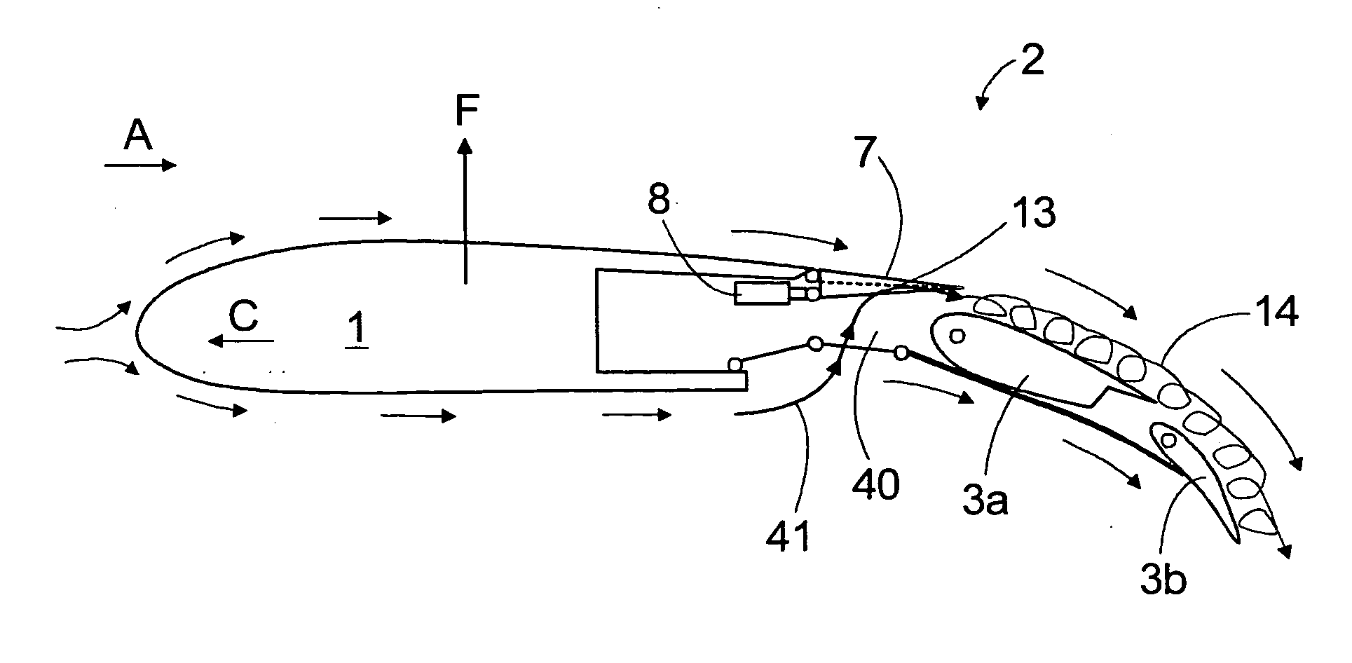
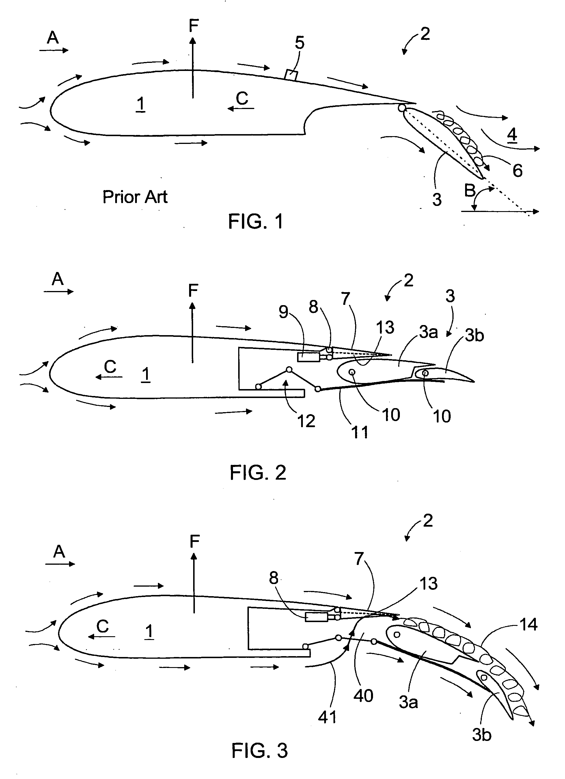
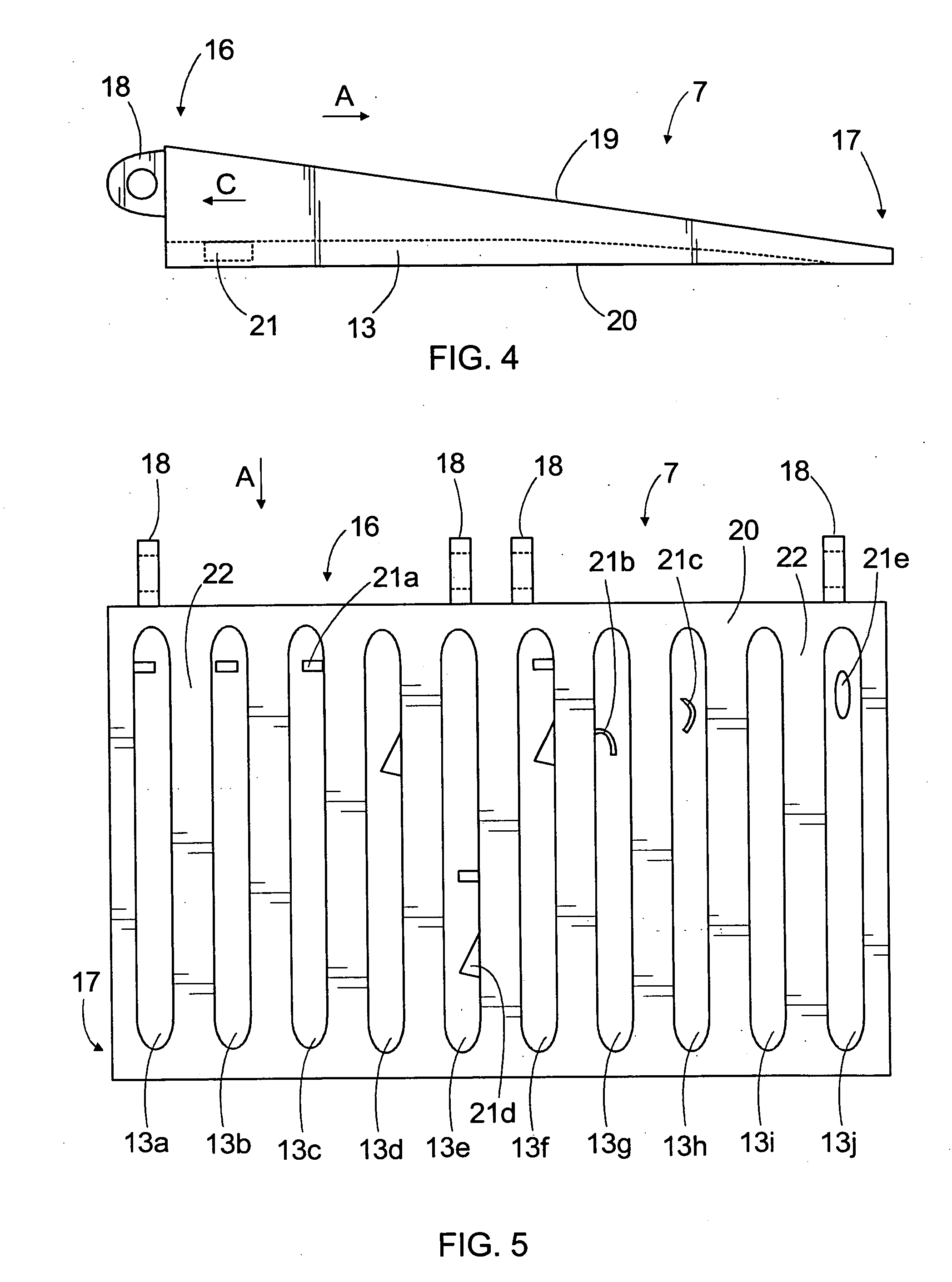
[0012] The invention provides the advantage that the grooves and vortex generators on the bottom surface of the spoiler are protected by the wing structures during cruising and, thus, do not cause air resistance during cruising. Only after the flaps are driven from the cruising position to the landing position, the grooves and vortex generators start to generate controlled vortexes in the airflow through the gap between the back portion of the wing and the flaps.
[0013] An essential idea of one embodiment of the invention is that the vortex generator is arranged to the groove in such a manner that it is entirely in the portion between the spoiler bottom surface and groove bottom and, thus, does not extend outside the bottom surface of the spoiler. This way, there is no need to reserve space for the vortex generators in the wing structures.

Problems solved by technology

One problem with the flaps is that airflow endeavors to leave the top surfaces of the flaps, which reduces the maximum upward force generated by the wing.
A drawback with such protruding vortex generators is, however, that they also cause vortexes and air resistance IL LABEL during cruising.

Method used


Image

  • Arrangement for generating vortexes
  • Arrangement for generating vortexes
  • Arrangement for generating vortexes

Examples


Embodiment Construction

[0031]FIG. 1 shows a wing 1 with a front edge and a back edge. A flap 3 on the back edge 2 is turned to its low position. When the intersecting angle B of the flap 3 and airflow A is large, the airflow on the top surface side of the wing 1 easily leaves the top surface of the flap 3, which reduces the maximum upward force F of the wing 1. FIG. 1 illustrates the leaving airflow with arrows 4. The leaving of the topside airflow can be delayed by arranging protruding vortex generators 5 on the wing to generate on the top surface side of the flap 3 controlled vortexes 6 that prevent the topside airflow from leaving the top surface at large intersecting angles. The direction of flight of the aircraft is marked with arrow C in the figure.

[0032]FIG. 2 shows a wing 1 equipped with a spoiler 7 of the invention. The spoiler 7 may have a predefined surface area and it may be arranged on the section between the back part of the wing 1 and the flaps 3 on the top surface side of the wing 1. Ther...


PUM


Abstract

A spoiler and wing of an aircraft. A bottom surface of the spoiler has several longitudinal, elongated grooves. At least some of the grooves are equipped with one or more vortex generators. Further, the invention relates to a wing having in its back part at least one flap and having at least one spoiler of the invention arranged on the section between the wing and flap. The invention also relates to a method and control surface for generating vortexes.

Description

BACKGROUND OF THE INVENTION [0001] The invention relates to a spoiler of an aircraft, which comprises: a top surface and a bottom surface; a front edge and a back edge that reside on the longitudinal outer edges of the spoiler; and at least one hinge element for turning the spoiler relative to said hinge element from a low position to a high position and vice versa. [0002] The invention further relates to a wing of an aircraft, which comprises: a front edge and a back edge; at least one movable flap at the back of the wing; at least one movable spoiler arranged on the front side of the flap, the spoiler comprising a top surface and a bottom surface; and at least one vortex generator for controlling airflows. [0003] The invention also relates to a movable control surface of an aircraft, which comprises: a top surface and a bottom surface; a front edge and a back edge that reside on the longitudinal outer edges of the control surface; and at least one hinge element for moving the cont...

Claims


Application Information

Patent Timeline
IPC IPC(8): B64C23/06
CPCY02T50/162B64C23/06Y02T50/10
Inventor KALLINEN, RISTO
Owner PATRIA AEROSTRUCTURES
Why Eureka
Eureka Blog
Learn More