Method for fabricating a rotor arrangement and a rotor arrangement for an electric machine

a technology of electric machines and rotors, which is applied in the direction of manufacturing stators/rotor bodies, magnetic circuit rotating parts, and shape/form/construction of magnetic circuits, etc., can solve the problems of excessive amount of magnetic material and large quantity of magnetic material, and achieve the effect of manufacturing at acceptable costs

Inactive Publication Date: 2005-10-20
MINEBEA CO LTD
View PDF21 Cites 24 Cited by
  • Summary
  • Abstract
  • Description
  • Claims
  • Application Information

AI Technical Summary

Benefits of technology

[0014] In another beneficial modification of the invention, the magnetizing coils generate magnetizing flux lines that run obliquely to the longitudinal direction of the rotor body in order to produce a skew in the magnetization of the permanent magnets, which results in a further reduction of cogging torque.
[0016] The arrangement according to the invention results in a considerable reduction in the amount of magnetic material required, particularly for rotors with low numbers of poles. Further, due to the spoke-like arrangement of the embedded permanent magnets made from isotropic material and their external magnetization, the permanent magnets can easily achieve Halbach magnetization, which has the advantages mentioned at the outset. The greater the number of permanent magnets or spokes per pole of the arrangement provided, the closer the magnetization can approximate an actual Halbach flux line distribution. By using isotropic magnetic material and external magnetizing coils, the required Halbach magnetization is automatically achieved without the need for theoretic model building and calculations for the design of the permanent magnets and the magnetizing device.

Problems solved by technology

For motors with a low number of poles, such a multi-pole permanent magnet ring has its disadvantages since the magnet wall has to have a substantial thickness which means that a considerable quantity of magnetic material is needed.
Although rotor arrangements having Halbach magnetization have numerous advantages, here again the problem arises that, with a low number of poles, the permanent magnet ring on the outer circumference of the rotor is comparatively thick, thus making an excessive amount of magnetic material necessary.

Method used


Image

  • Method for fabricating a rotor arrangement and a rotor arrangement for an electric machine
  • Method for fabricating a rotor arrangement and a rotor arrangement for an electric machine
  • Method for fabricating a rotor arrangement and a rotor arrangement for an electric machine

Examples


Embodiment Construction

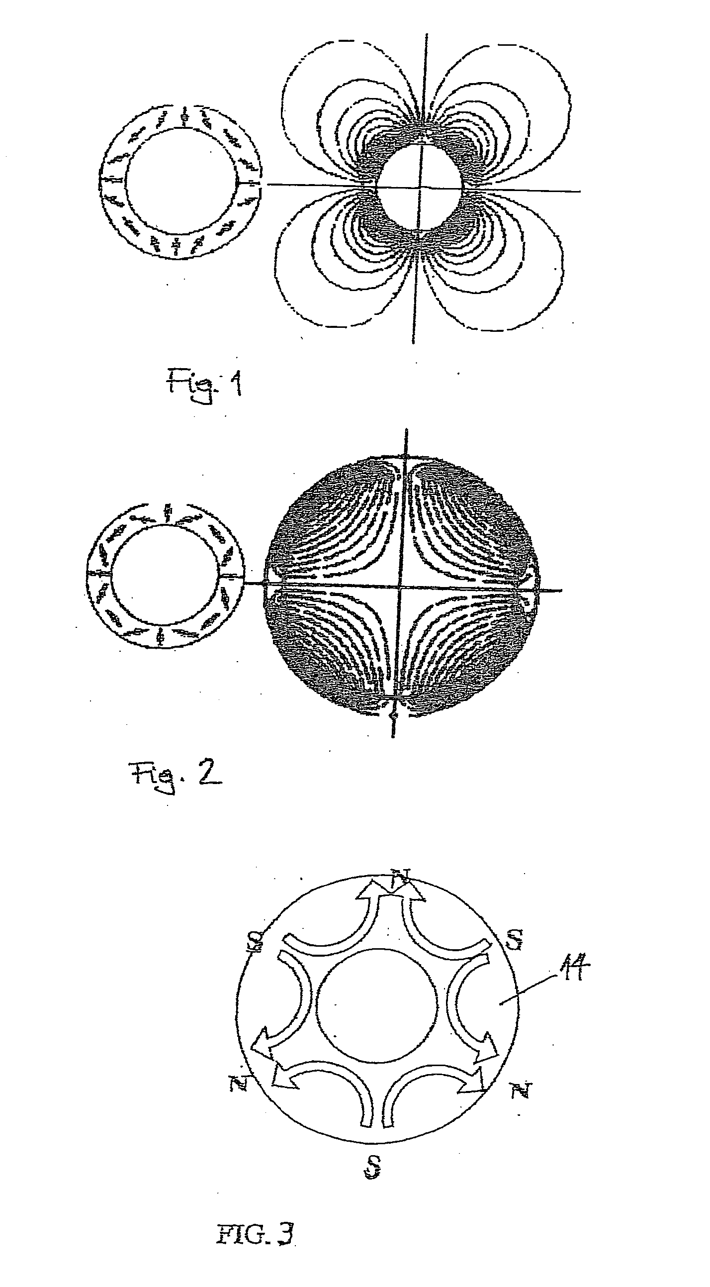
[0024]FIGS. 1 and 2 show the magnetization and the corresponding flux line distribution for the permanent magnet ring of a rotor arrangement according to an inner rotor motor configuration (FIG. 1) and an outer rotor motor configuration (FIG. 2) respectively. In the case of a Halbach magnetization, the flux line distribution in the air gap between rotor and stator is inherently sine shaped, as a result of which theoretical minimum cogging torque is achieved and an essentially sine-shaped EMF waveform is produced. Since, due to the Halbach magnetic arrangement, the magnetic flux lines within the rotor are guided with hardly any leakage flux and thus practically shielded from one side, the permanent magnet ring can be mounted onto a rotor body that does not need an iron back yoke, as can be seen from the flux line distribution in FIGS. 1 and 2.

[0025]FIG. 3 schematically shows the multi-pole magnetization of a magnetic ring 14 of a rotor arrangement having Halbach magnetization. As ca...


PUM

PropertyMeasurementUnit
isotropic magneticaaaaaaaaaa
magnetizationaaaaaaaaaa
magnetic field distributionaaaaaaaaaa

Abstract

A method for fabricating a rotor arrangement for an electric machine in which a rotor body is provided and permanent magnets made from an isotropic magnetic material are embedded in the rotor body, the permanent magnets being magnetized by an external magnetizing device with a magnetization that corresponds at least approximately to a Halbach magnetic field distribution.

Description

FIELD OF THE INVENTION [0001] The invention relates to a method for fabricating a rotor arrangement for an electric machine and a corresponding rotor arrangement. The rotor arrangement according to the invention can be generally employed in such electric machines as DC motors and generators. BACKGROUND OF THE INVENTION [0002] A large variety of electric motors is known on the market, all of which can be classified in various ways, such as according to their structure, their drive mechanism, their control mode, etc. A preferred field of application for the invention is in brushless DC motors and other permanent magnet motors, it being basically known to provide permanent magnets on the outer circumference of a rotor body or to embed them in the rotor body. The invention can further be employed in electric motors and generators that can be configured as inner rotor motors or as outer rotor motors. Electric motors having an inner rotor motor configuration have a rotor arrangement that ...

Claims


Application Information

Patent Timeline
Patent Type & Authority Applications(United States)
IPC IPC(8): H02K15/03H02K1/27H02K1/30H02K15/00H02K15/02H02K15/14H02K21/12H02K21/14
CPCH02K1/2733H02K1/2766H02K1/2786Y10T29/49012H02K15/03H02K21/14Y10T29/49009H02K1/30H02K1/2792
Inventor KLOEPZIG, MARKUSPOPOV, VLADIMIR VLADIMIROVICH
Owner MINEBEA CO LTD
Why Eureka
Try Eureka