
Method and system for bidirectional data and power transmission

a power transmission and bidirectional technology, applied in the direction of signal transmission/receiving via power distribution, resistance welding apparatus, electric signalling details, etc., can solve the problems of increasing the weight of the system, consuming power, and disadvantages of microprocessors,

Inactive Publication Date: 2005-10-20
USRG HOLDCO IX
View PDF27 Cites 19 Cited by
  • Summary
  • Abstract
  • Description
  • Claims
  • Application Information

AI Technical Summary

Benefits of technology

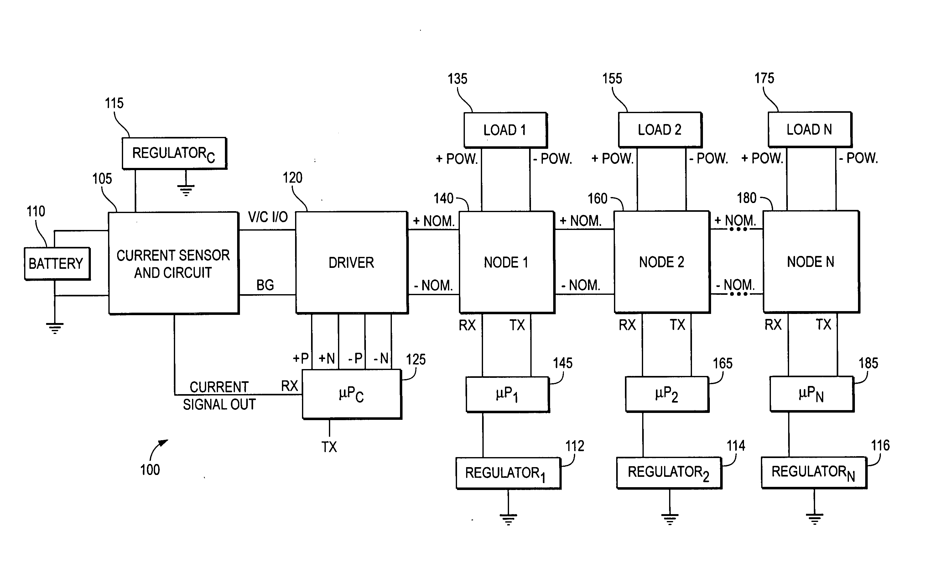
"The present invention provides a method and system for supplying power and transmitting data through a single set of wires. This is achieved using a high-speed power transistor bridge to switch voltage polarity and an active current sink at the nodes. The controller and nodes use microprocessors for processing the signals sent and received. The system includes a pair of wires, a power source, a controller, and multiple nodes. The controller sends signals to the nodes using a driver comprising a power transistor bridge. The power transistor bridge is capable of switching the voltage polarity from the power source on the set of wires in response to different voltage control signals from the controller microprocessor. The technical effect of this invention is the efficient use of wires for both power and data transmission, reducing the complexity of the system and simplifying the installation process."

Problems solved by technology

There are, however, some disadvantages to the use of microprocessors.
A look under the hood of a newer automobile may be enough to see one disadvantage to microprocessor use: before microprocessors became small enough and reliable enough to be installed in automobiles, it was possible to see how separate engine parts were connected, and even to see the road underneath.
Extra wires and cables are disadvantageous: every extra wire installed consumes power and adds weight.
More wires also make maintenance harder.
Unfortunately, it has been largely impossible for wires to be eliminated from most microprocessor system designs.

Method used


Image

  • Method and system for bidirectional data and power transmission
  • Method and system for bidirectional data and power transmission
  • Method and system for bidirectional data and power transmission

Examples


first embodiment

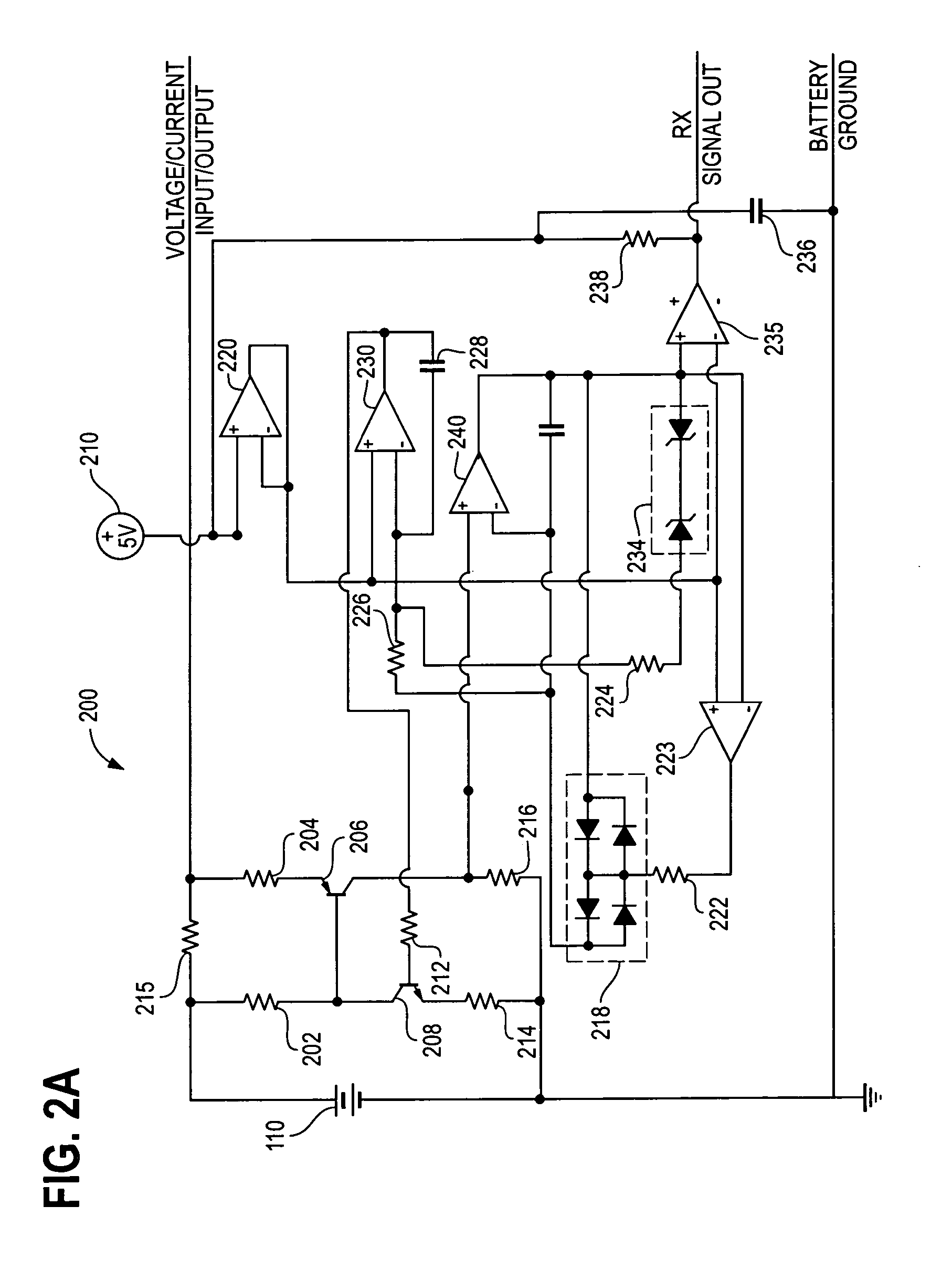
[0022]FIG. 3B shows a circuit diagram of a driver, in accordance with an embodiment of the present invention;

second embodiment

[0023]FIG. 3C shows a circuit diagram of a driver, in accordance with an embodiment of the present invention;

[0024]FIG. 4A shows a circuit diagram of a first embodiment of a node, in accordance with an embodiment of the present invention;

[0025]FIG. 4B shows a circuit diagram of a second embodiment of a node, in accordance with an embodiment of the present invention;

[0026]FIG. 5A shows a cross-sectional view of an embodiment of the present invention in which a system has been installed in an automobile;

[0027]FIG. 5B shows a perspective view of the automobile, in accordance with an embodiment of the present invention;

[0028]FIG. 6 shows an embodiment of the invention in which a system has been installed in a military aircraft;

[0029]FIG. 7 shows an embodiment of the invention in which a system has been installed in an office building;

[0030]FIG. 8 shows an embodiment of a controller microprocessor, in accordance with an embodiment of the present invention;

[0031]FIG. 9 shows a timi...


PUM

PropertyMeasurementUnit
impedanceaaaaaaaaaa
voltageaaaaaaaaaa
impedanceaaaaaaaaaa

Abstract

A method and system for bidirectional data and power transmission are shown and described. An exemplary embodiment comprises a current receiver, including a microprocessor and a driver, and a plurality of nodes connected to the current receiver through a plurality of wires that allow both power supply and bidirectional data transfer between the current receiver and the plurality of nodes. The use of the plurality of wires for both power and data transmission offers significant advantages over the prior art in terms of weight reduction and system modularity.

Description

CROSS-REFERENCE TO RELATED PATENT APPLICATIONS [0001] This application is a divisional of copending U.S. patent application Ser. No. 10 / 607,230, filed Jun. 26, 2003, now allowed.FIELD OF THE INVENTION [0002] This invention generally relates to methods and systems for distributing electrical power and data. In particular, the invention relates to a method and system for transmitting power and data using a single set of wires. BACKGROUND OF THE INVENTION [0003] Microprocessors are found in almost every electronic device that we use in our day-to-day lives. One important application of microprocessors has been in the control of electronic devices installed in vehicles, including automobiles, buses, and airplanes. In the past, many critical automobile functions have been accomplished mechanically. Automobile functions such as like wheel differential adjustments and engine timing are now controlled using sensors and actuators electrically connected to microprocessors. [0004] Microprocess...

Claims


Application Information

Patent Timeline
Patent Type & Authority Applications(United States)
IPC IPC(8): H04B3/54
CPCH04B3/54H04B3/548H04B2203/5491H04B2203/5458H04B2203/547H04B2203/5425H04L5/14H04M11/04H04L25/02
Inventor HAIR, JAMES M. IIIGREENE, DANIEL L.
Owner USRG HOLDCO IX
Learn More