Optical device that measures distance between the device and a surface

a technology of optical devices and distances, applied in the direction of distance measurement, static indicating devices, instruments, etc., can solve problems such as problems such as problems such as problems such as optical navigation

Active Publication Date: 2005-10-20
PIXART IMAGING INC
View PDF10 Cites 68 Cited by
  • Summary
  • Abstract
  • Description
  • Claims
  • Application Information

AI Technical Summary

Problems solved by technology

However, optical navigation can be problematic in certain applications that involve three-dimensional movements.

Method used


Image

  • Optical device that measures distance between the device and a surface
  • Optical device that measures distance between the device and a surface
  • Optical device that measures distance between the device and a surface

Examples


Embodiment Construction

[0015] Reference will now be made in detail to various embodiments in accordance with the invention, examples of which are illustrated in the accompanying drawings. While the invention will be described in conjunction with these embodiments, it will be understood that they are not intended to limit the invention to these embodiments. On the contrary, the invention is intended to cover alternatives, modifications and equivalents, which may be included within the spirit and scope of the invention as defined by the appended claims. Furthermore, in the following detailed description of the invention, numerous specific details are set forth in order to provide a thorough understanding of the invention. In other instances, well known methods, procedures, components, and circuits have not been described in detail as not to unnecessarily obscure aspects of the invention.

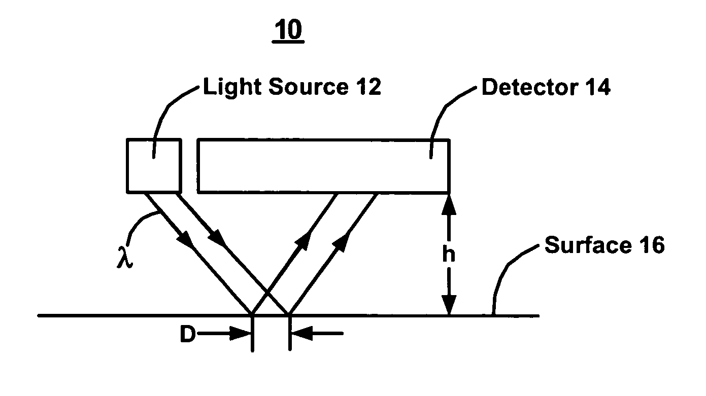
[0016]FIG. 1 is a block diagram showing elements of an optical device 10 in one embodiment in accordance with the inventi...


PUM


Abstract

An optical device and methods thereof are described. The device includes a first light source adapted to emit light onto a surface, and a detector adapted to receive light reflected from the surface. The reflected light produces a speckle pattern. The distance between the optical device and the surface can be measured using a quantifiable attribute associated with the speckle pattern.

Description

BACKGROUND ART [0001] Optical navigation devices conventionally use a laser-generated light that reflects off a surface to a detector. The detector includes, for example, a complementary metal-oxide semiconductor (CMOS) imager array. The reflection of the light produces a pattern of speckle that is captured by the CMOS imager. As the device is moved relative to the surface (or vice versa), successive images are rapidly captured and compared to determine the amount of movement. The rate at which images are captured can be used to determine the velocity of movement. [0002] Optical navigation devices generally perform well for tracking two-dimensional movements. For example, an optical mouse very precisely tracks movement along the surface of a mouse pad. However, optical navigation can be problematic in certain applications that involve three-dimensional movements. [0003] Consider, for example, an optical pen that is being used to translate and display a user's handwritten input. As t...

Claims


Application Information

Patent Timeline
Patent Type & Authority Applications(United States)
IPC IPC(8): G01C3/06G01D5/30G06F3/03G06F3/033
CPCG01D5/30G06F3/03545G06F3/0346G06F3/0317
Inventor DEPUE, MARSHALL THOMASSCHROEDER, DALE W.XIE, TONG
Owner PIXART IMAGING INC
Why Eureka
Try Eureka