Method and system for reshaping the cornea

a corneal reshaping and corneal technology, applied in the field of focused energy delivery systems, can solve the problems of corneal stromal tissue not healing optimally without further treatment, surgical procedures alone may not solve every optical aberration, etc., and achieve the effect of stiffening the stromal tissu

Inactive Publication Date: 2010-04-01
TECHNOLAS PERFECT VISION
View PDF21 Cites 39 Cited by
  • Summary
  • Abstract
  • Description
  • Claims
  • Application Information

AI Technical Summary

Benefits of technology

[0007]For the present invention, the system further includes an element for holding the contour surface of a selected contact lens against the surface of the cornea, after a laser procedure has been performed. While the holding element may include a mechanical apparatus such as a suction ring with a holder, more often it will simply be the patient's eyelid. Typically, in use, each contact lens will be held against the cornea for a pre-determined time duration (e.g., eight hours). As each contact lens is held against the surface of the material, in sequence, for a respective time duration, the material becomes slightly reconfigured. Eventually, with the last contact lens in the sequence, the corneal surface is shaped into the desired configuration.
[0008]In accordance with the present invention, the system also includes a mechanism for applying a softening agent to the cornea. Preferably, the softening agent includes enzymes and can be applied before the initial contact lens is applied to the eye, while a contact lens is held to the cornea, and / or after a contact lens is removed and before the next contact lens is applied. Further, the system includes a device for applying a curing agent to the cornea. For instance, the applicator device may be a dropper that coats the corneal surface with a curing agent, such as Riboflavin, that will penetrate the corneal surface. Additionally, the system is provided with a unit for radiating UV light onto the coated surface and into the material to interact with the curing agent. Importantly, through this interaction the curing agent and UV light cross-link and stiffen the stromal tissue in the cornea. Preferably, UV light is radiated into the cornea after the final contact lens has been held against the cornea for the respective pre-determined time duration.
[0009]Before use of the laser unit in the present invention, the cornea is measured for a refractive error. As a result, diagnostic data is received regarding the refractive error. Thereafter, the diagnostic data is inputted into a mathematical model to obtain geometrical parameters for the laser procedure. Specifically, these geometrical parameters define a spot pattern, or a series of spot patterns, that are to be performed during the laser procedure. As a result of the laser procedure, the cornea is weakened by the disruption of intrastromal stress distributions. As noted above, however, the corneal configuration may change due to biomechanical forces in the eye after the laser procedure. Therefore, the cornea must somehow be constrained, or guided, to its eventual desired configuration. In order to ensure that the weakened cornea responds to the laser procedure as required for vision correction, each successive contact lens provides a known mechanical force to the corneal surface. In this manner, the corneal surface is reshaped to the desired configuration.

Problems solved by technology

For some laser procedures, however, the corneal stromal tissue may not heal in an optimal manner without further treatment.
In view of the complexity of the cornea's internal structure and its related biomechanical properties, it is not surprising that surgical procedures alone may not resolve every optical aberration.

Method used


Image

  • Method and system for reshaping the cornea
  • Method and system for reshaping the cornea
  • Method and system for reshaping the cornea

Examples


Embodiment Construction

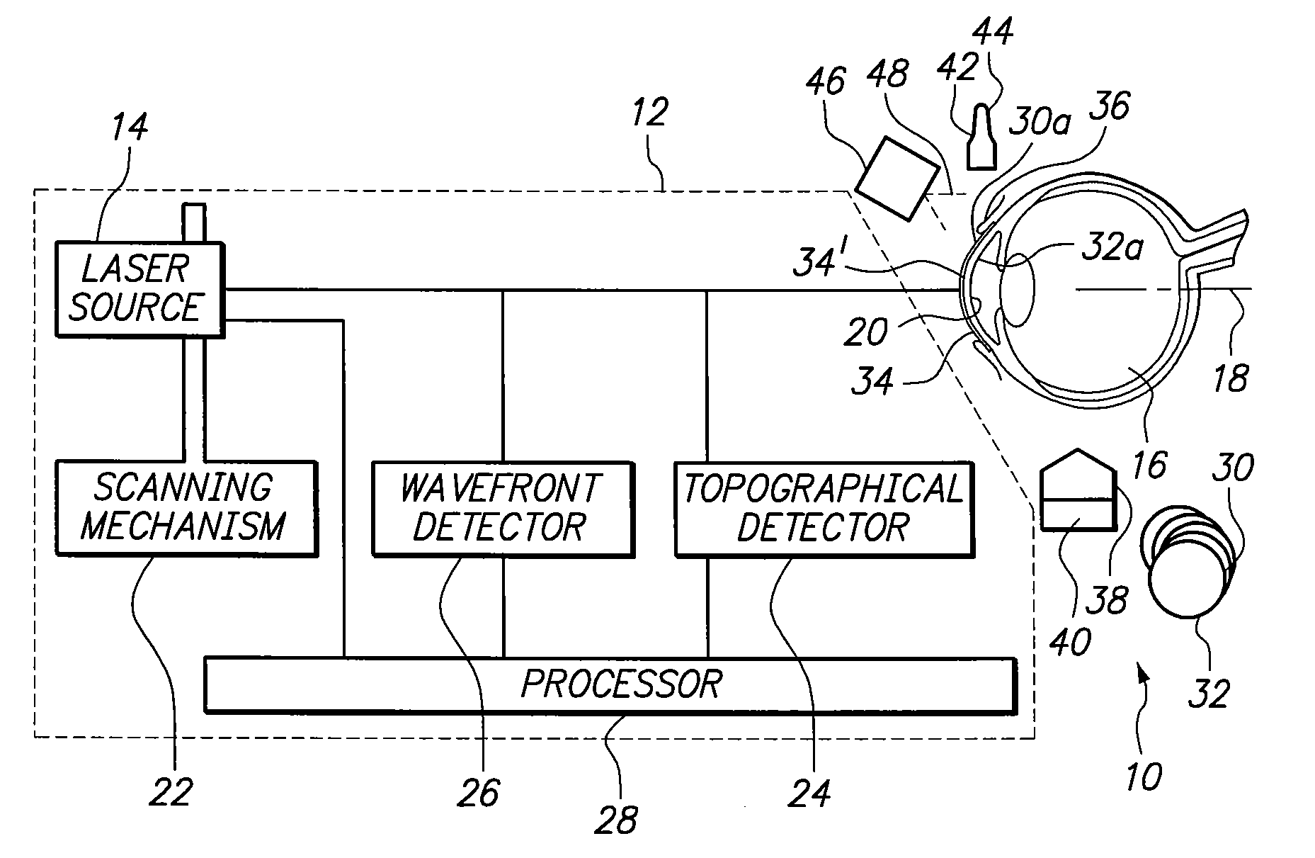
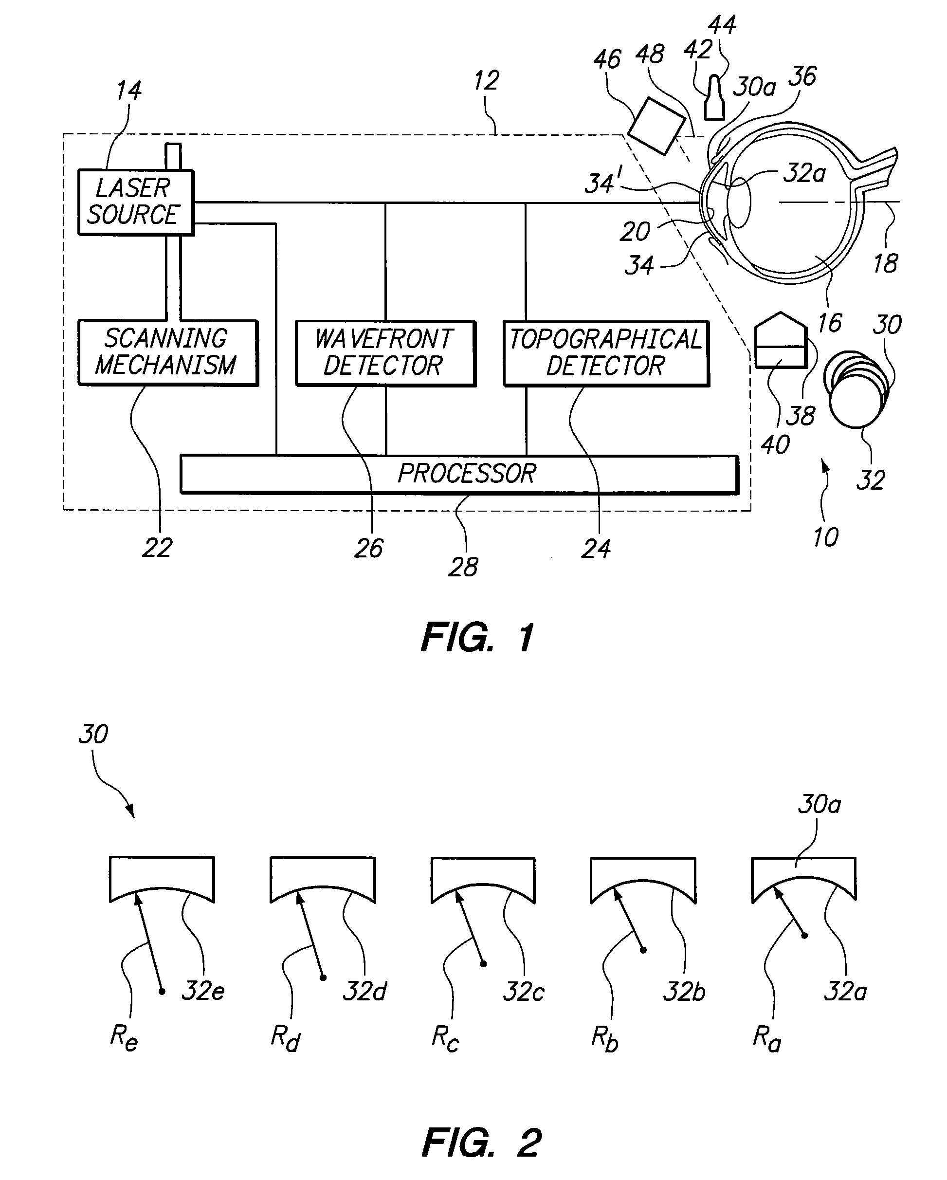
[0014]Referring initially to FIG. 1, a system in accordance with the present invention is shown schematically and generally designated 10. As shown, the system 10 includes a laser unit 12 provided with a laser source 14 to generate a laser beam. Further, the laser source 14 is positioned relative to the eye 16 to allow a laser beam to be directed along a beam path that is collinear with the optical axis 18 of the eye 16. For the present invention, the laser unit 12 may treat the corneal tissue 20 by means of ablation, disruption, chemical decomposition and / or combinations thereof. In certain embodiments, to perform a laser procedure to treat corneal tissue 20, the laser source 14 may have a mode in which the laser source 14 generates a continuous train of ultra-short pulses, with each pulse having a pulse duration in a femto-second range. For laser procedures involving intrastromal photoablation of corneal tissue, e.g., laser induced optical breakdown, each pulse will have an energy...


PUM


Abstract

A system and method are provided for reshaping the surface of a resilient transparent material such as a cornea. In the system, a laser unit generates a femto-second laser beam to deliver focused energy inside the material. Specifically, the energy is focused over a defined spot pattern to weaken the material. Further, the system includes a contact element that forms a contour surface. In order to reshape the material, the system provides for holding the contour surface of the contact element against the surface of the weakened material. After holding the contour surface against the material for a pre-determined time duration, the surface of the material is reshaped with a desired configuration that substantially mimics the contour surface of the contact element.

Description

FIELD OF THE INVENTION[0001]The present invention pertains generally to systems for delivering focused energy inside a resilient transparent material. More particularly, the present invention pertains to a laser system for delivering radiation to weaken a material, and to a contact element for holding the material in a desired configuration as the material sets after the laser procedure. The present invention is particularly, but not exclusively, useful for reshaping the surface of the resilient transparent material to improve the optical performance of the resilient transparent material.BACKGROUND OF THE INVENTION[0002]There are many laser procedures in which it is desirable to modify the optical performance of a resilient transparent material. Typically, these procedures require a reconfiguration of the material. For a variety of laser procedures, the desired results are obtained immediately and no further operations or treatments are required. For some laser procedures, however, ...

Claims


Application Information

Patent Timeline
Patent Type & Authority Applications(United States)
IPC IPC(8): A61F9/01
CPCA61F9/0079A61F9/00827A61F2009/00853G02C7/047A61F2009/0088A61F2009/00882A61F2009/00872
Inventor PANTHAKEY, DARYUSGLASMACHER, MATHIASLOESEL, FRIEDER
Owner TECHNOLAS PERFECT VISION
Why Eureka
Try Eureka