
Method for preparing micro optical element on quartz glass substrate by applying femto-second laser

A technology of quartz glass and femtosecond laser, which is used in cleaning methods using liquids, optical components, chemical instruments and methods, etc., can solve the problems of large difference in photothermal characteristics, expensive and difficult to obtain photosensitive glass, etc. Excellent optical and electrical properties, fast polishing results

Inactive Publication Date: 2009-11-04
SHANGHAI INST OF OPTICS & FINE MECHANICS CHINESE ACAD OF SCI
View PDF0 Cites 35 Cited by
  • Summary
  • Abstract
  • Description
  • Claims
  • Application Information

AI Technical Summary

Problems solved by technology

This method requires multiple complex annealing treatments, and this Foturan photosensitive glass is expensive and difficult to obtain, and its photothermal properties are far behind those of fused silica materials, so it is not suitable for optical element processing applications. Method for fabricating micro-optical elements in quartz glass remains unresolved

Method used

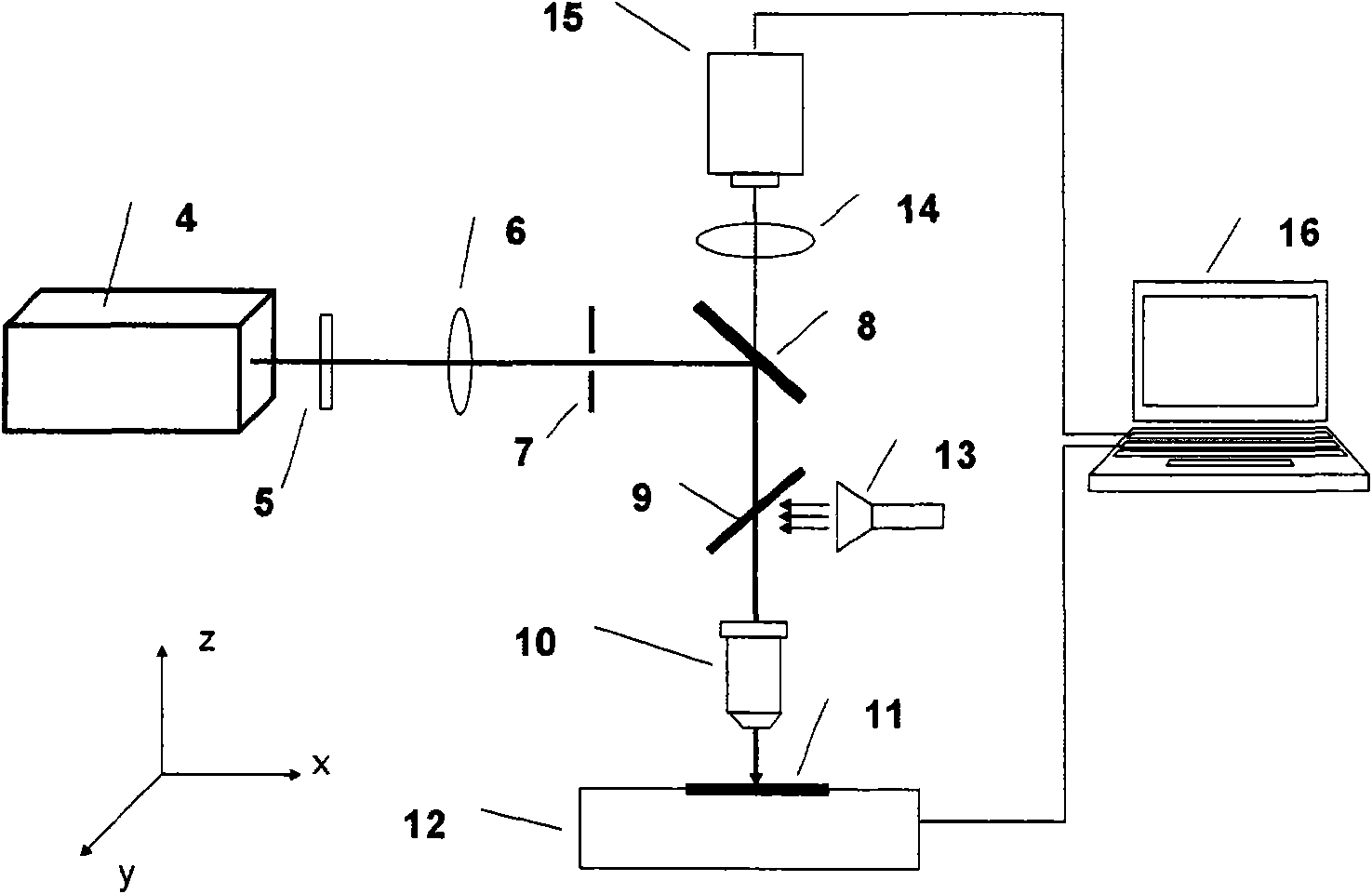

Image

  • Method for preparing micro optical element on quartz glass substrate by applying femto-second laser
  • Method for preparing micro optical element on quartz glass substrate by applying femto-second laser
  • Method for preparing micro optical element on quartz glass substrate by applying femto-second laser

Examples


Embodiment 1

[0037] Embodiment 1: Micromirror preparation

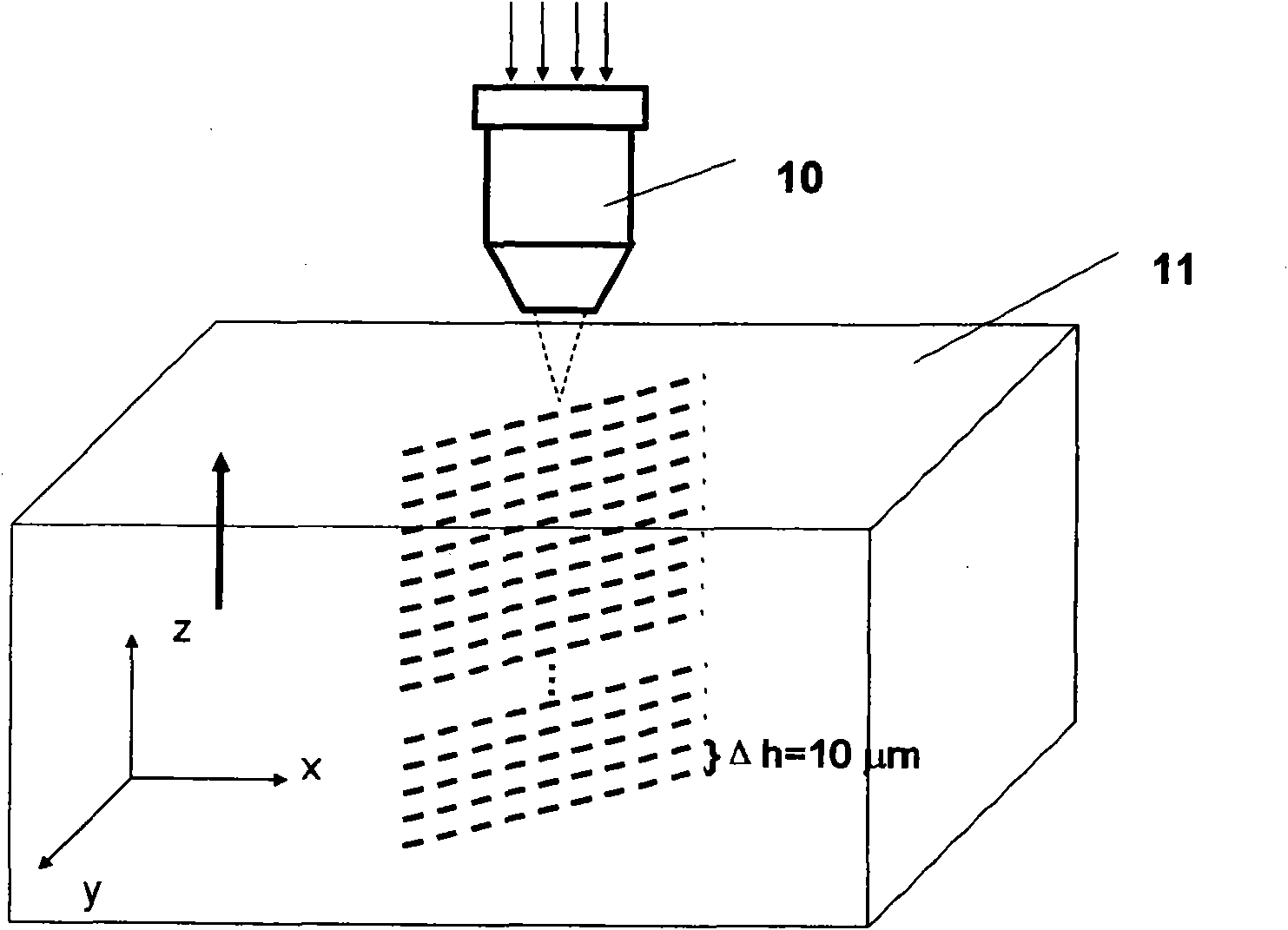
[0038]When scanning the profile of the micromirror, parallel lines need to be layered and scanned from the lower surface of the quartz glass substrate from the bottom to the upper surface. The distance between them is Δh=10μm, such as image 3 As shown, the three-dimensional precision platform is moved along the -z direction by 10 μm and then scanned and irradiated in a straight line. After femtosecond laser irradiation, the quartz glass sample was placed in 10% hydrofluoric acid aqueous solution and assisted by ultrasonic cleaning for about 3 hours, until the femtosecond laser irradiation area was selectively etched away. Take out the glass sample, clean it ultrasonically with alcohol, dry it, place it on the high-temperature refractory brick, and use a hydrogen-oxygen torch to polish the microlens area for about 5 minutes. The flame temperature should be close to but not exceeding the softening temperature of quartz glass at 17...

Embodiment 2

[0039] Embodiment 2: microlens preparation

[0040] When scanning the profile of the microlens, it is necessary to decompose the profile of the microlens into a cylindrical surface and a microsphere, and scan them sequentially with a femtosecond laser. When scanning the cylindrical surface, according to the condition of layered scanning of the three-dimensional pattern in the present invention, the distance between two adjacent layers of parallel circular surfaces is selected as Δh=10 μm, such as Figure 4 As shown, the three-dimensional precision platform is moved 10 μm along the z direction to perform circular scanning irradiation; when scanning the spherical surface of the microlens, since the radius of each layer of the ring is not the same, in order to enable the laser to irradiate uniformly, the scanning microlens In the process of lensing, it is necessary to keep the arc length between two adjacent scanning layers as Δs=2μm ( Figure 5 ) remains unchanged, if the radiu...


PUM


Abstract

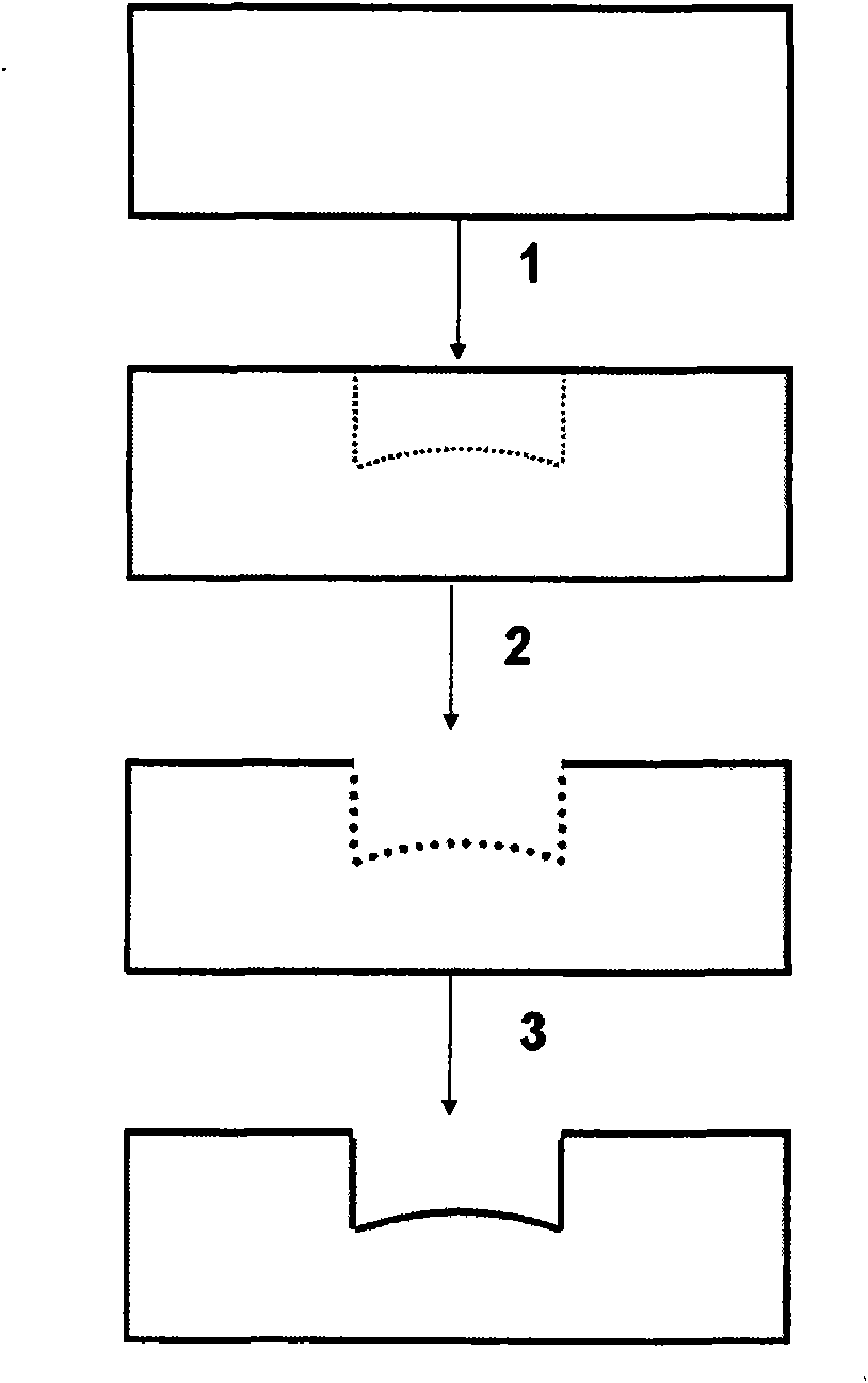
The invention relates to a method for preparing a micro optical element on a quartz glass substrate by applying femto-second laser, which is characterized by comprising three steps of femto-second laser irradiation, chemical etching and hydrogen-oxygen flame polishing. The method can achieve processing of any surface types including a plane, a standard spherical surface, a non-spherical surface and the like; and the step of the hydrogen-oxygen flame polishing only has a generated product of water, thus the method is environment-friendly, has quick polishing, avoids physical contacts and chemical reactions at the same time, and solves the difficulty which cannot be solved by a common polishing wheel because the high temperature of the flame can repair lattice damages caused by micro-machining.

Description

technical field [0001] The invention relates to the processing of micro-optical elements, in particular to a method for preparing micro-optic elements on a quartz glass substrate by using a femtosecond laser. Background technique [0002] Micro-optical components, especially micro-lenses and micro-lens arrays, are widely used in lithography systems, optical microscopic imaging, optical communications and other fields. In recent years, they have played an important role in lab-on-a-chip systems. Its manufacturing process is mainly soft etching technology (see J.Chen, W.Wang et al., J.Micromech.Microeng., Vol.14, P 675, 2004) or imprinting technology (see C.Chang, S. Yang et al., Rapid fabrication of ultraviolet-cured polymer microlens arrays by softroller stamping process.Microelectronic Engineering, Vol.84, P 355, 2007), etc., the substrate materials used are mainly transparent organic polymer materials, while other such as ion beam processing Although the processing precis...

Claims


Application Information

Patent Timeline
IPC IPC(8): G02B3/00G03F7/00B08B3/12C03B29/00C03C15/00
Inventor 何飞程亚林锦添徐至展
Owner SHANGHAI INST OF OPTICS & FINE MECHANICS CHINESE ACAD OF SCI
Learn More