High intensity MHz mode-locked laser

a mode-locked laser and high-intensity technology, applied in semiconductor lasers, laser details, optical resonator shape and construction, etc., to achieve the effect of high peak power and low cos

Active Publication Date: 2009-09-15
RES FOUNDATIN OF THE UNIV OF CENT FLORIDA INC
View PDF20 Cites 29 Cited by
  • Summary
  • Abstract
  • Description
  • Claims
  • Application Information

AI Technical Summary

Benefits of technology

[0011]It is a primary objective of the present invention to provide a

Problems solved by technology

A typical mode-locked laser design is shown in FIG. 1; the laser of this design has drawbacks in tha

Method used


Image

  • High intensity MHz mode-locked laser
  • High intensity MHz mode-locked laser
  • High intensity MHz mode-locked laser

Examples


Embodiment Construction

[0038]Before explaining the disclosed embodiments of the present invention in detail, it is to be understood that the invention is not limited in its application to the details of the particular arrangements shown since the invention is capable of further embodiments. Also, the terminology used herein is for the purpose of description and not of limitation.

[0039]Acronyms and terminology used throughout this description are defined as follows:

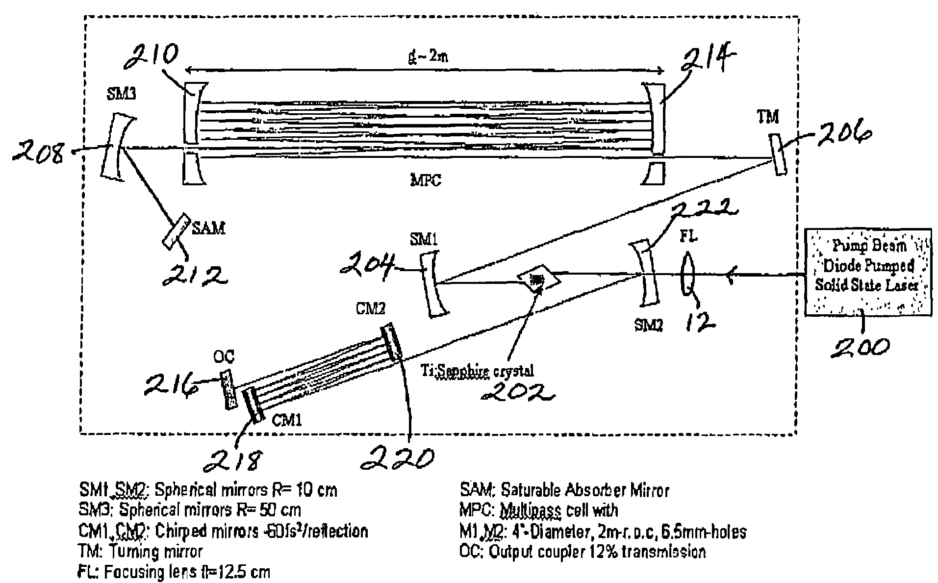
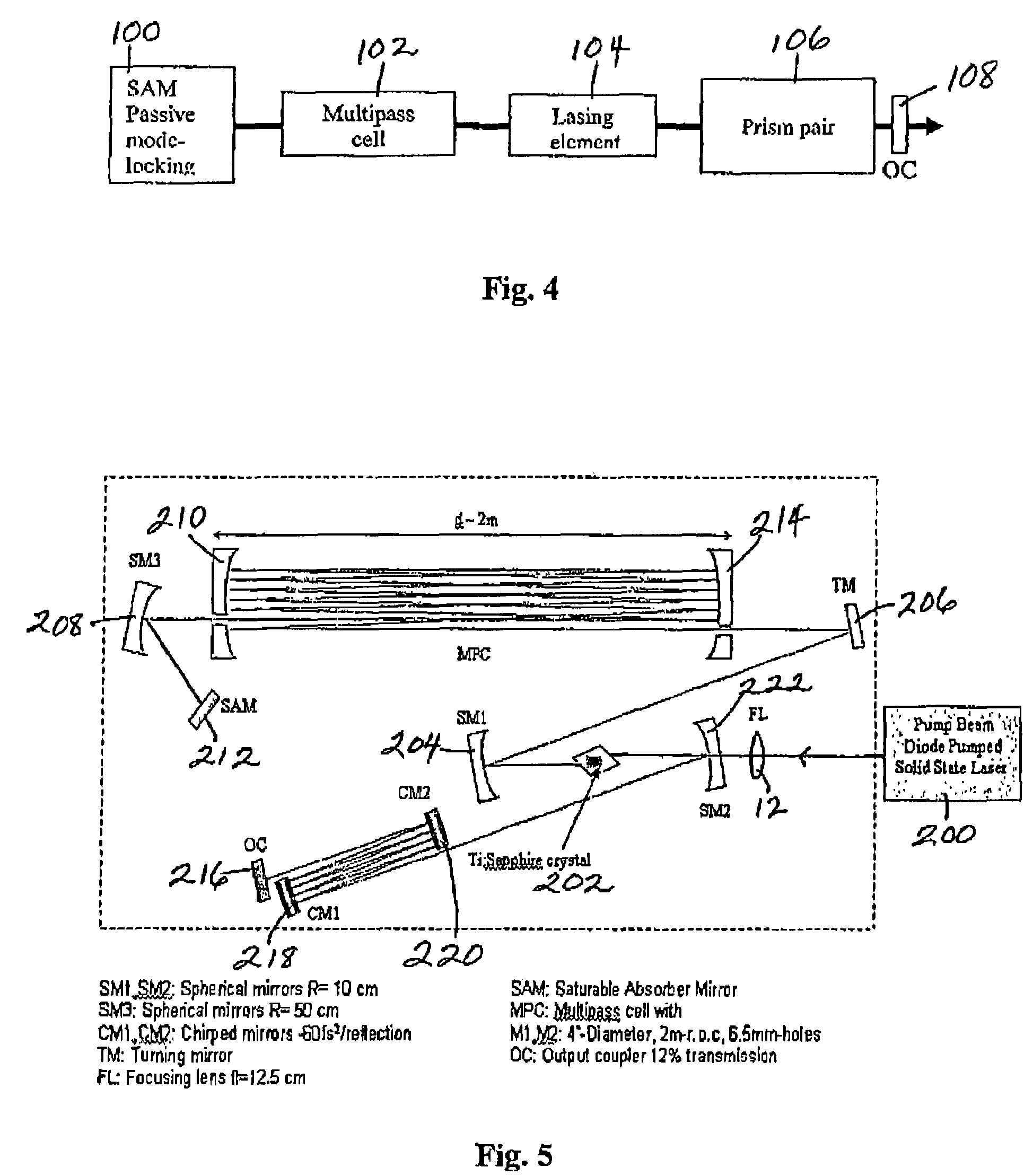
[0040]CM—Chirped mirrors that are able to provide second- and third-order dispersion compensation using a scheme where each frequency component is reflected at different depths through the dielectric coating, which consists of multiple stacks of varying thickness. Chirped mirrors provide very robust and compact arrangements for the design of ultrafast lasers.

[0041]FL—focusing lens used to focus the pump beam inside the laser crystal

[0042]KLM—Kerr lens mode-locking

[0043]MHz—megahertz

[0044]MPC—Multipass Cell—a cell inserted inside the laser cavity...


PUM


Abstract

Systems, configurations and methods of using an ultrafast, self-starting, mode-locked laser are provided. The systems, devices and methods of using stable, self-starting mode-locked lasers, can be compact, use fewer optical elements and have energies sufficient for most micro-processing and micro-structuring applications. The large spectral bandwidth of ultra-short (femtosecond) laser pulses can be used in laser sensing applications, micro-machining, time-resolved experiments, where short-lived transient species can be observed in biological or chemical reactions. Terahertz radiation can be generated using ultrashort pulses and used for imaging applications.

Description

[0001]This invention claims the benefit of priority based on the U.S. Provisional Application Ser. No. 60 / 571,907 filed May 17, 2004, the contents of which are incorporated herein by reference.FIELD OF THE INVENTION[0002]This invention relates to ultrafast mode-locked lasers generating pulses with picosecond or less in duration, and, more particularly to systems, devices and methods of using stable, self-starting mode-locked lasers, which are compact, use fewer optical elements and have energies sufficient for most micro-processing and micro-structuring applications.BACKGROUND AND PRIOR ART[0003]Extremely short duration optical pulses, which are also known as femtosecond pulses, are important for high speed signal processing, communications, micro-machining, imaging, sensing applications, time resolved experiments, where short-lived transient species can be observed in biological and chemical reactions.[0004]The early development of laser technology involving the production of extre...

Claims


Application Information

Patent Timeline
IPC IPC(8): H01S3/098
CPCH01S3/1118H01S3/08059H01S3/08068H01S3/0811H01S3/0813H01S3/1636H01S3/1103H01S3/1625H01S3/094038
Inventor RICHARDSON, MARTINZOUBIR, ARNAUD
Owner RES FOUNDATIN OF THE UNIV OF CENT FLORIDA INC
Why Eureka
Try Eureka