Optical system and method

a technology of optical system and optical filter, applied in the field of optical filter, can solve the problems of reducing the maximum sqrt(n) reduction of speckle and/or other interference patterns, and affecting the quality of optical filter, etc., and achieve the effect of reducing the speckle contrast ratio

Inactive Publication Date: 2011-05-05
OPTYKA
View PDF14 Cites 42 Cited by
  • Summary
  • Abstract
  • Description
  • Claims
  • Application Information

AI Technical Summary

Benefits of technology

[0009]According to a first aspect of the invention, there is provided an optical system comprising: a coherent light source; optical elements for directing light from the source to a target, said optical elements including at least one diffusing element arranged to reduce a coherence volume of light from the source and a variable opt

Problems solved by technology

Speckle and/or other interference patterns arise through constructive and destructive interference when spatially and/or temporally coherent light is scattered by transmission through, or reflection from, a rough surface.
Problems associated with solutions that depend on rotation, translation, and/or vibration of an optical element include size, scale, weight, cost, and power consumption.
A problem associated with many a

Method used


Image

  • Optical system and method
  • Optical system and method
  • Optical system and method

Examples


Embodiment Construction

[0032]The invention will be more clearly understood from the following description of some embodiments thereof, given by way of example only, with reference to the accompanying drawings, in which:—

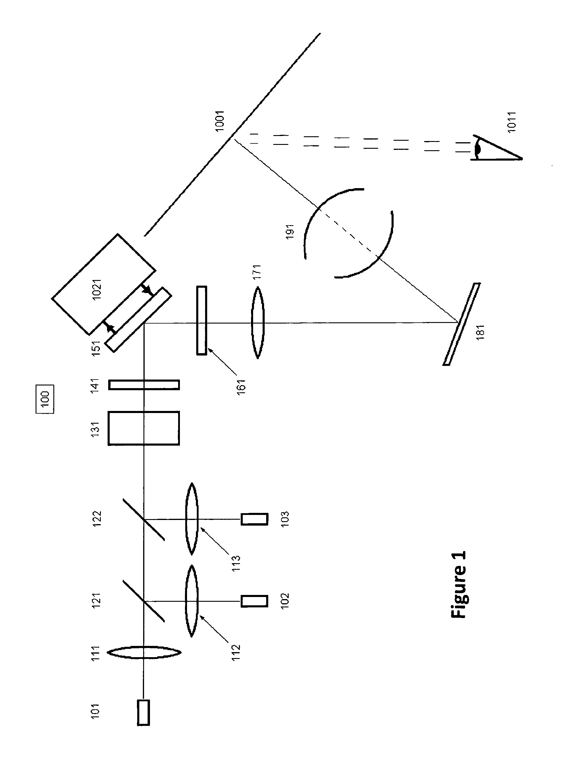
[0033]FIG. 1 illustrates a projection display system 100 in accordance with an embodiment of the present invention;

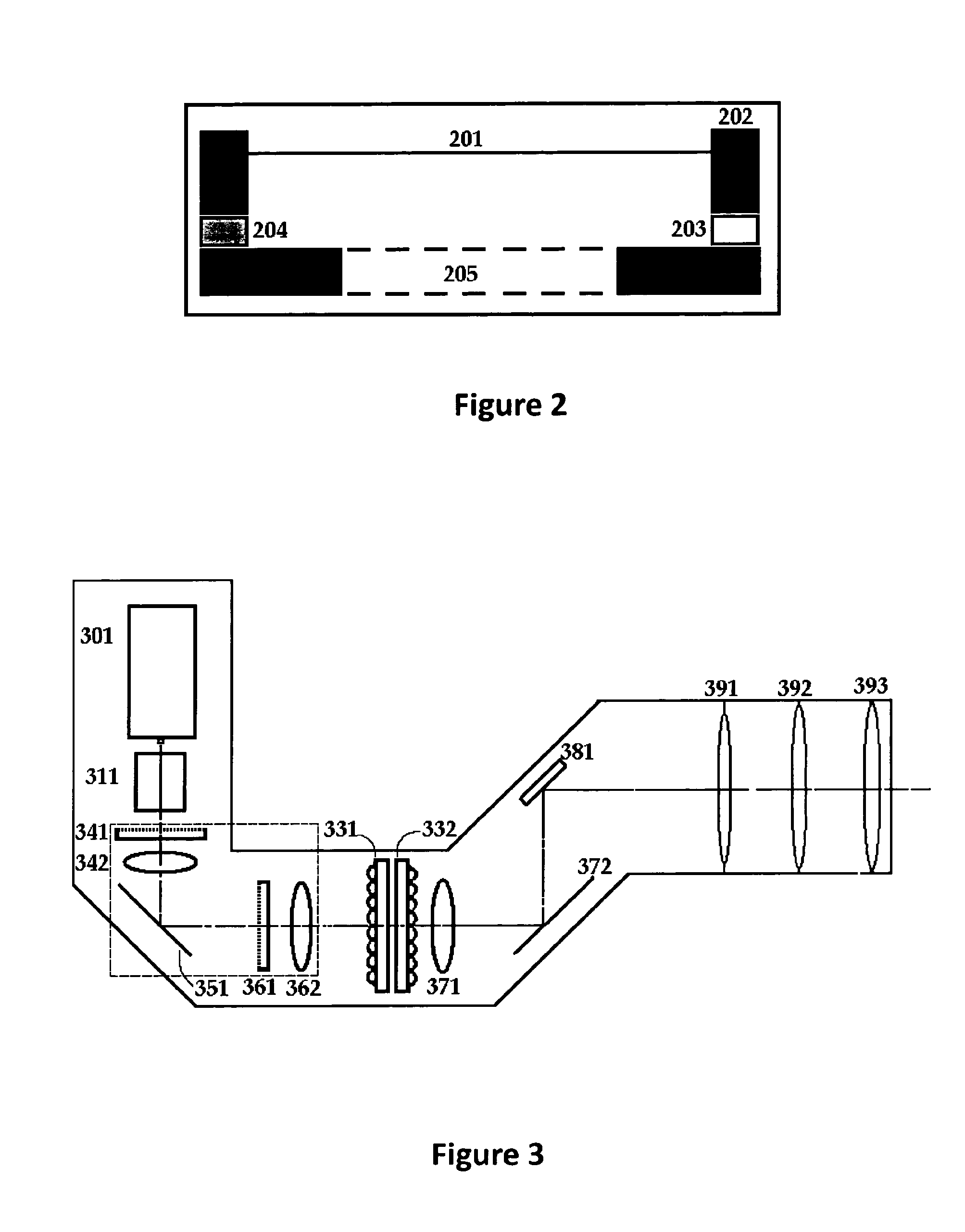
[0034]FIG. 2 illustrates various elements of a deformable mirror 200 of the system;

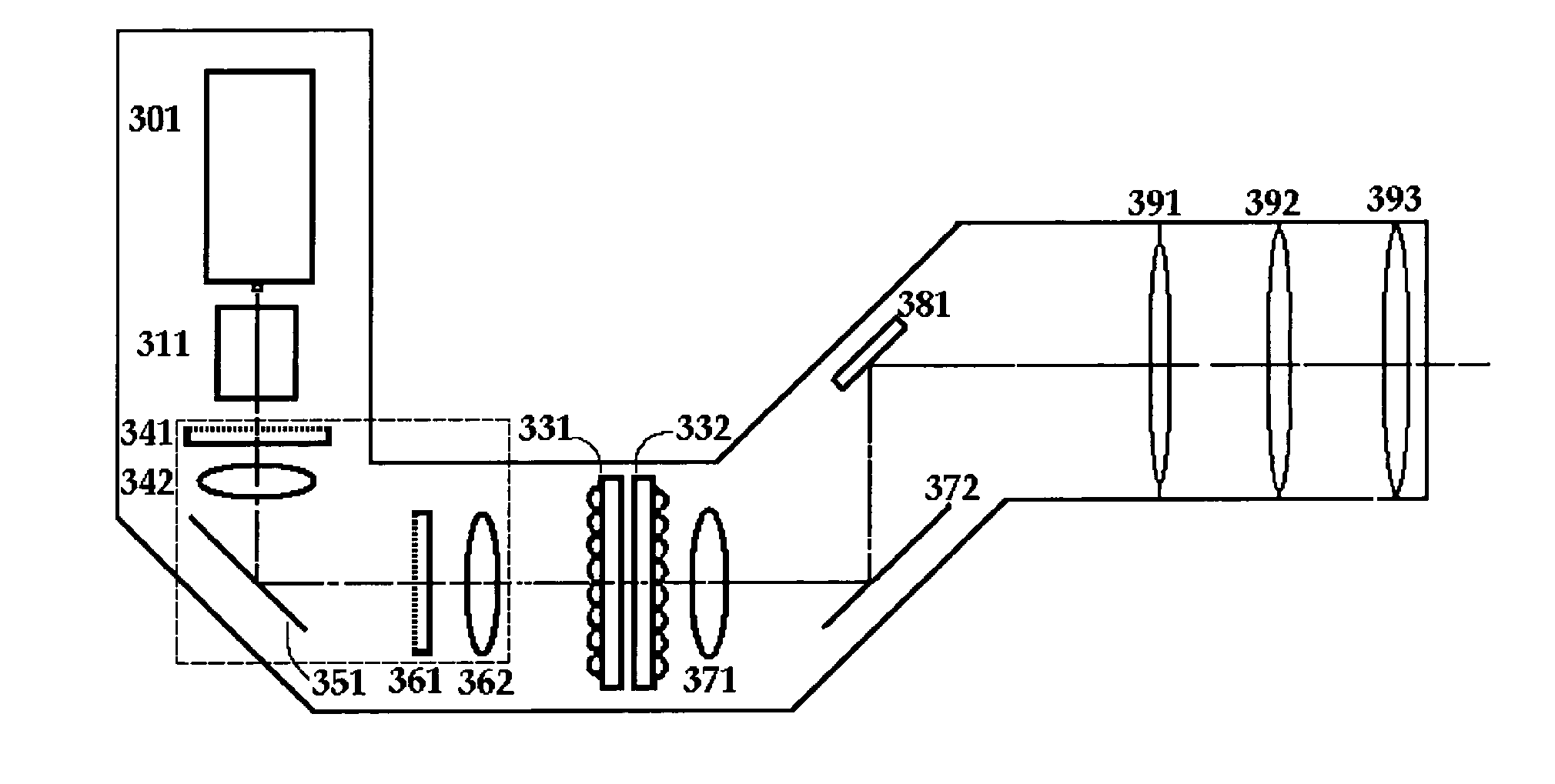
[0035]FIG. 3 illustrates elements of projection display system that uses a fly's eye illumination intensity homogenisation and beam shaping optical system;

[0036]FIG. 4 illustrates elements of a projection display system that uses a fly's eye optical system and three source image colour field forming microdisplays;

[0037]FIGS. 5A, 5B, and 5C illustrate various elements of a deformable mirror sensing system according to the invention;

[0038]FIG. 6 illustrates elements of a projection display system that uses a beam-shaping holographic optical element as a diffuser and for uniform light intensity dis...


PUM


Abstract

An optical system (100) comprises a coherent light source (101) and optical elements for directing light from the source to a target (1001). The optical elements include at least one diffusing element (141, 161) arranged to reduce a coherence volume of light from the source and a variable optical property element (151). A control system (1021) controls the variable optical property element such that different speckle patterns are formed over time at the target (1001) with a temporal frequency greater than a temporal resolution of an illumination sensor or an eye (1011) of an observer so that speckle contrast ratio in the observed illumination is reduced. The variable optical property element (151) may be a deformable mirror with a vibrating thin plate or film.

Description

INTRODUCTION[0001]The present invention relates to the field of illumination systems using spatially and / or temporally coherent light sources. More particularly, the present invention relates to the reduction of speckle and / or other interference patterns observed in images displayed, areas illuminated, and images acquired using coherent light sources, most particularly, using a deformable mirror to reduce speckle.[0002]Speckle and / or other interference patterns arise through constructive and destructive interference when spatially and / or temporally coherent light is scattered by transmission through, or reflection from, a rough surface. In this context, we consider the term speckle as synonymous with interference patterns. We understand the term “coherent” to mean spatially and / or temporally coherent. We use the term “coherence volume” to mean a correlated region within a beam of light where speckle can arise.[0003]Speckle is manifest as bright and dark granular and / or more structur...

Claims


Application Information

Patent Timeline
IPC IPC(8): G02B27/48G02B26/08G03B21/14
CPCG02B5/02G02B26/0825G02B26/0833G02B26/0858H04N9/3197G02B27/48H04N9/3111H04N9/3161H04N9/3164G02B27/0938
Inventor SHEVLIN, FERGAL PATRICKSQALLI, OMARDESCHARMES, NICOLAS
Owner OPTYKA
Why Eureka
Try Eureka