
Low reflectivity LCD with cop retarder and cop matching rm

a low reflectivity, retarder technology, applied in the field of displays, can solve the problems of reducing the contrast ratio of the display, degrading image quality, and not being able to simply replace the linear polariser with the circular polariser in the display, so as to improve the appearance of high ambient lighting, improve the effect of low ambient light image quality and high quality

Active Publication Date: 2019-09-12
SHARP KK
View PDF2 Cites 4 Cited by
  • Summary
  • Abstract
  • Description
  • Claims
  • Application Information

AI Technical Summary

Benefits of technology

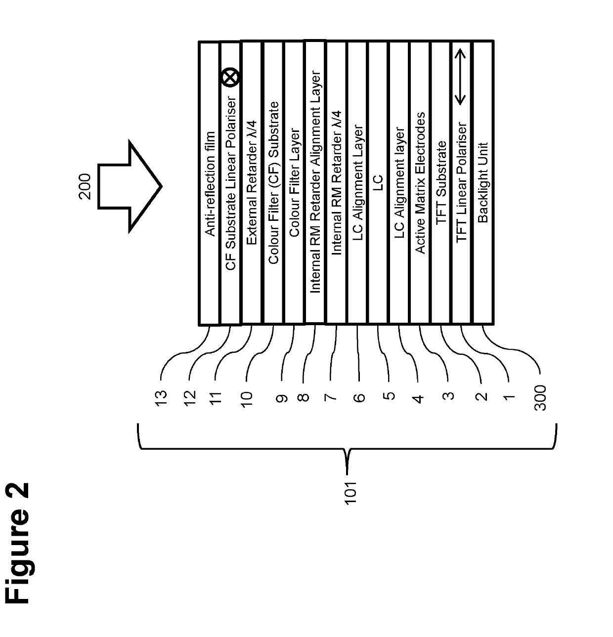
The present invention provides a liquid crystal display (LCD) that reduces unwanted ambient light reflections from internal display components, while maintaining high contrast ratio and image quality in both low and high ambient lighting conditions. The LCD includes a plurality of layers, including a first linear polarizer, an external retarder, a colour filter substrate, a colour filter layer, an internal reactive mesogen (RM) retarder alignment layer, an internal RM retarder, a liquid crystal (LC) layer, and a second linear polarizer. The external retarder and the internal RM retarder are configured to cancel each other's polarization control function for all wavelengths transmitted by the LCD, thus ensuring high contrast ratio for images viewed in dark room conditions. The addition of the internal RM retarder and the external retarder to an LCD that is conventionally operated with two linear polarisers results in an LCD configured for optimum low ambient light image quality and improved high ambient lighting appearance.

Problems solved by technology

While light transmitted by the display from the backlight to the viewer is modulated by the LC layer as expected to give the intended transmission, in conventional configurations unwanted ambient light reflected from internal layer interfaces is re-emitted (reflected) without control in all LC states, resulting in reduced contrast ratio for the display and degraded image quality.
However, it is not possible to simply replace the linear polarisers for circular polarisers in displays such as FFS, IPS, and TN displays without significantly degrading the image quality.

Method used


Image

  • Low reflectivity LCD with cop retarder and cop matching rm
  • Low reflectivity LCD with cop retarder and cop matching rm
  • Low reflectivity LCD with cop retarder and cop matching rm

Examples


Embodiment Construction

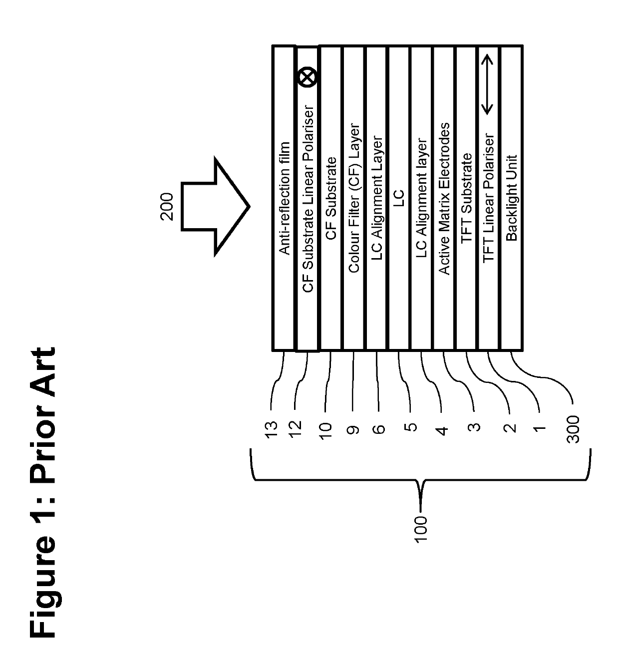
[0019]For comparison purposes for illustrating the enhancements of the present invention, FIG. 1 is a schematic drawing of an optical stack arrangement of an LCD as is conventional in the art. Referring to FIG. 1, a transmissive FFS or IPS type LCD 100 of a conventional configuration, which may be considered standard in the art, typically comprises an optical stack configuration in which the liquid crystal (LC) material 5 is sandwiched between a TFT substrate 2 and colour filter (CF) substrate 10 with a uniform cell gap of typically 3-5 μm. First and second LC alignment layers 4 and 6 are disposed on the inner surfaces of the TFT substrate and CF substrate adjacent to the LC material to promote a uniform, antiparallel planar alignment of the LC. A colour filter (CF) layer 9 is disposed on the colour filter substrate 10, and an active-matrix pixel array and drive electronics 3 are disposed on the inner surface of the thin film transistor (TFT) substrate 2. Linear polarisers 1 and 12 ...


PUM

PropertyMeasurementUnit
azimuthal angleaaaaaaaaaa
thicknessaaaaaaaaaa

Abstract

A liquid crystal device (LCD) is configured for minimizing unwanted internal ambient light reflections. The LCD includes a plurality of layers, the layers comprising from a viewing side: a first linear polariser; an external retarder that is made of a cyclic olefin polymer (COP) material or a cyclic olefin copolymer (COC) material; a colour filter substrate; a colour filter layer; an internal reactive mesogen (RM) retarder alignment layer; an internal reactive mesogen (RM) retarder; a liquid crystal (LC) layer; and a second linear polarizer. The external retarder and the internal RM retarder are configured such that the optical properties (for example light polarization control function) of the external retarder and the internal retarder are matched to negate each other for light passing through the external retarder and the internal RM retarder. The LCD simultaneously maintains high image quality in both high and low ambient lighting conditions.

Description

TECHNICAL FIELD[0001]The present invention has application within the field of displays which are particularly suitable for outdoor use and other comparable potentially high ambient illumination situations.BACKGROUND ART[0002]In recent years, the performance of transmissive or emissive type displays, such as liquid crystal displays (LCDs) and organic light-emitting diode displays (OLEDs), has increased significantly in metrics such as resolution, colour gamut capability and brightness. Such displays also have decreased in cost such that they now form the large majority of the electronic displays market for most applications, both static and mobile, indoor and outdoor use. This has resulted in the retreat of reflective and transflective display types into niche applications for very high ambient illumination applications, and long battery life requirement applications.[0003]Even applications which until very recently a reflective display technology was preferred, such as outdoor sign...

Claims


Application Information

Patent Timeline
Patent Type & Authority Applications(United States)
IPC IPC(8): G02F1/13363G02F1/1335G02F1/1337G02F1/1339
CPCG02F1/133528G02F2001/133531G02F2413/11G02F1/13363G02F1/133711G02F2001/133334G02F2413/02G02F2001/133633G02F1/133514G02F2001/133357G02F2001/133638G02F1/13394G02F2001/133726G02F2413/06G02F1/133633G02F1/133634G02F1/133334G02F1/133565G02F1/133638C09K2323/00C09K2323/03G02F1/133357G02F1/133531G02F1/133726
Inventor SMITH, NATHAN JAMESACREMAN, ANDREWHOPKIN, HYWELMINOURA, KIYOSHIMURATA, KOJIKAWAHIRA, YUICHISAKAI, AKIRAYU, JIYUN
Owner SHARP KK
Learn More