
Light source module, display device having the same, and a method thereof

a technology of light source module and display device, which is applied in the direction of static indicating device, non-linear optics, instruments, etc., can solve the problems of degrading light leakage, and the inability to display images and operate the display panel. , to achieve the effect of reducing the contrast ratio of the display panel, and reducing the display panel

Inactive Publication Date: 2009-06-11
SAMSUNG ELECTRONICS CO LTD
View PDF3 Cites 4 Cited by
  • Summary
  • Abstract
  • Description
  • Claims
  • Application Information

AI Technical Summary

Benefits of technology

[0006]Since a flat display panel, such as a liquid crystal display (“LCD”) panel, requires a separate light source to provide light to the display panel, there are disadvantages in displaying images and in operating the display panel. For example, the light source may constantly or evenly supply light having a substantially uniform luminance to an entire surface of the display panel, thereby degrading a contrast ratio of the display panel. The contrast ratio of the display panel may be degraded because the light source supplies the display panel with the light having predetermined luminance, thereby causing light leakage even when the display panel displays images corresponding to black images. Moreover, the light source consumes a relatively large portion of the power in the display panel. Since a conventional light source is turned on and off together with a driving of the display panel, it is difficult to reduce an overall power consumption of the light source.
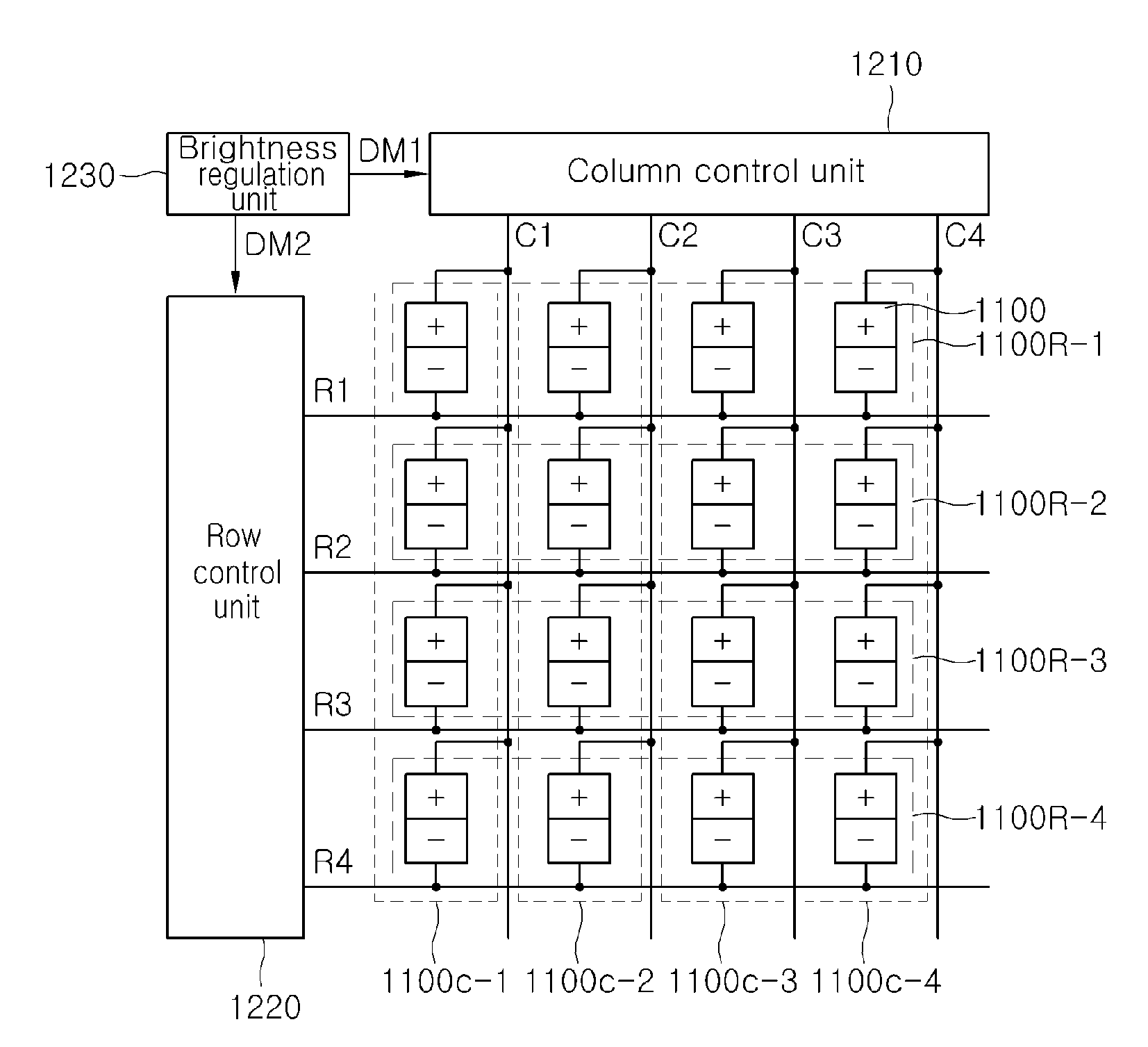
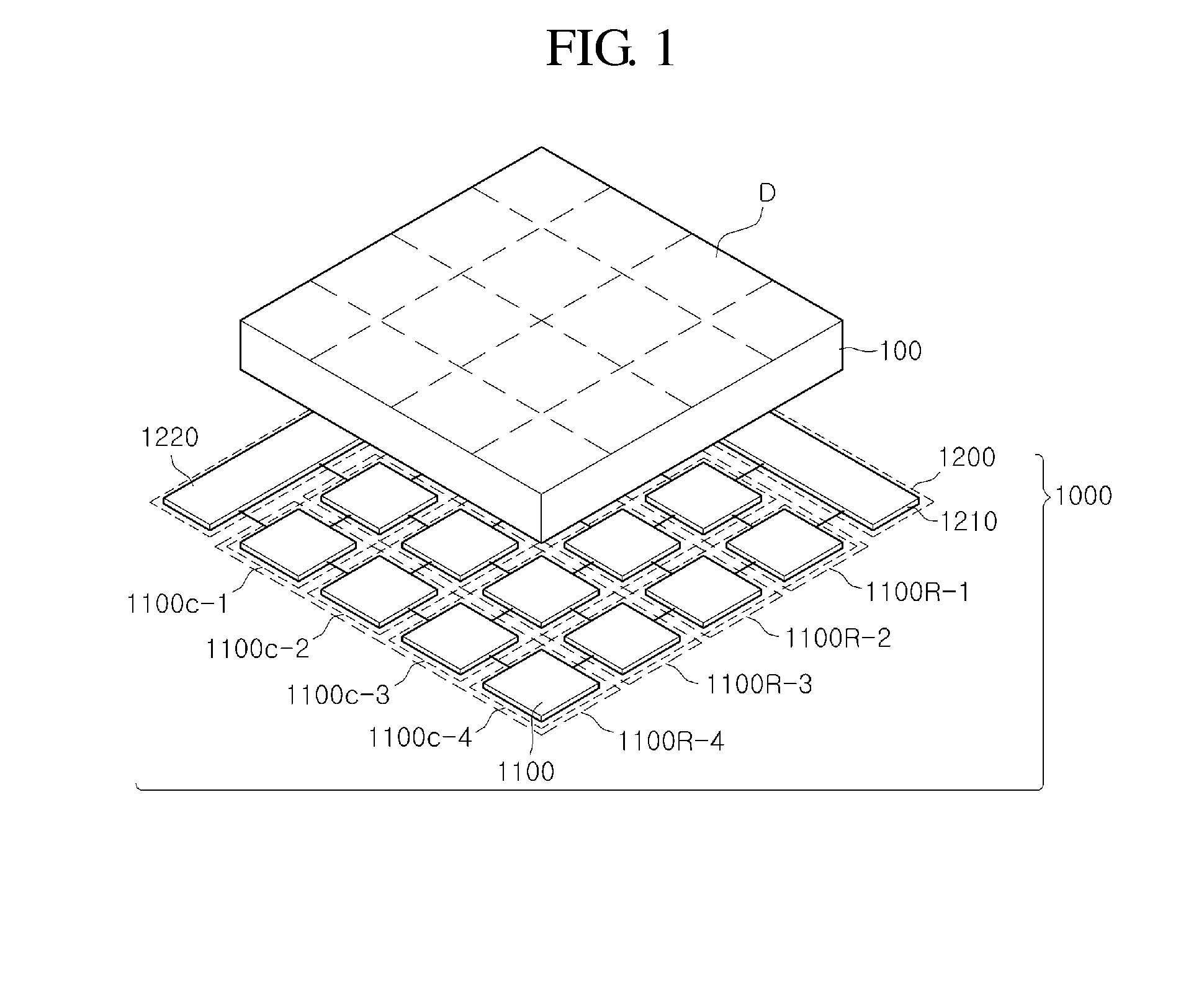
[0007]An exemplary embodiment provides a light source module, a driving method of the light source module, and a display device including the light source module. A brightness of light outputted from a plurality of the light source units, which independently emit light, is controlled according to images of corresponding regions of a display panel of the display device, to thereby improve a contrast ratio. The light source units emit light in a row or column direction for one frame period according to the images of the corresponding blocks, to thereby reduce power consumption,
[0008]An exemplary embodiment provides a light source module, which can reduce or prevent discharge interference that may occur when a plurality of light source units are manufactured with a surface light source region divided, a driving method of the light source module, and a display device including the light source module.

Problems solved by technology

Since a flat display panel, such as a liquid crystal display (“LCD”) panel, requires a separate light source to provide light to the display panel, there are disadvantages in displaying images and in operating the display panel.
The contrast ratio of the display panel may be degraded because the light source supplies the display panel with the light having predetermined luminance, thereby causing light leakage even when the display panel displays images corresponding to black images.
Moreover, the light source consumes a relatively large portion of the power in the display panel.
Since a conventional light source is turned on and off together with a driving of the display panel, it is difficult to reduce an overall power consumption of the light source.

Method used


Image

  • Light source module, display device having the same, and a method thereof
  • Light source module, display device having the same, and a method thereof
  • Light source module, display device having the same, and a method thereof

Examples


Embodiment Construction

[0046]Hereinafter, exemplary embodiments of the present invention will be described in detail with reference to the accompanying drawings. However, the present invention is not limited to the embodiments disclosed below but may be implemented into different forms. These embodiments are provided only for illustrative purposes and for full understanding of the scope of the present invention by those skilled in the art. In the drawings, the size and relative sizes of layers and regions may be exaggerated for clarity.

[0047]It will be understood that when an element or layer is referred to as being “on” or “connected to” another element or layer, the element or layer can be directly on or connected to another element or layer or intervening elements or layers. In contrast, when an element is referred to as being “directly on” or “directly connected to” another element or layer, there are no intervening elements or layers present. Like numbers refer to like elements throughout. As used he...


PUM


Abstract

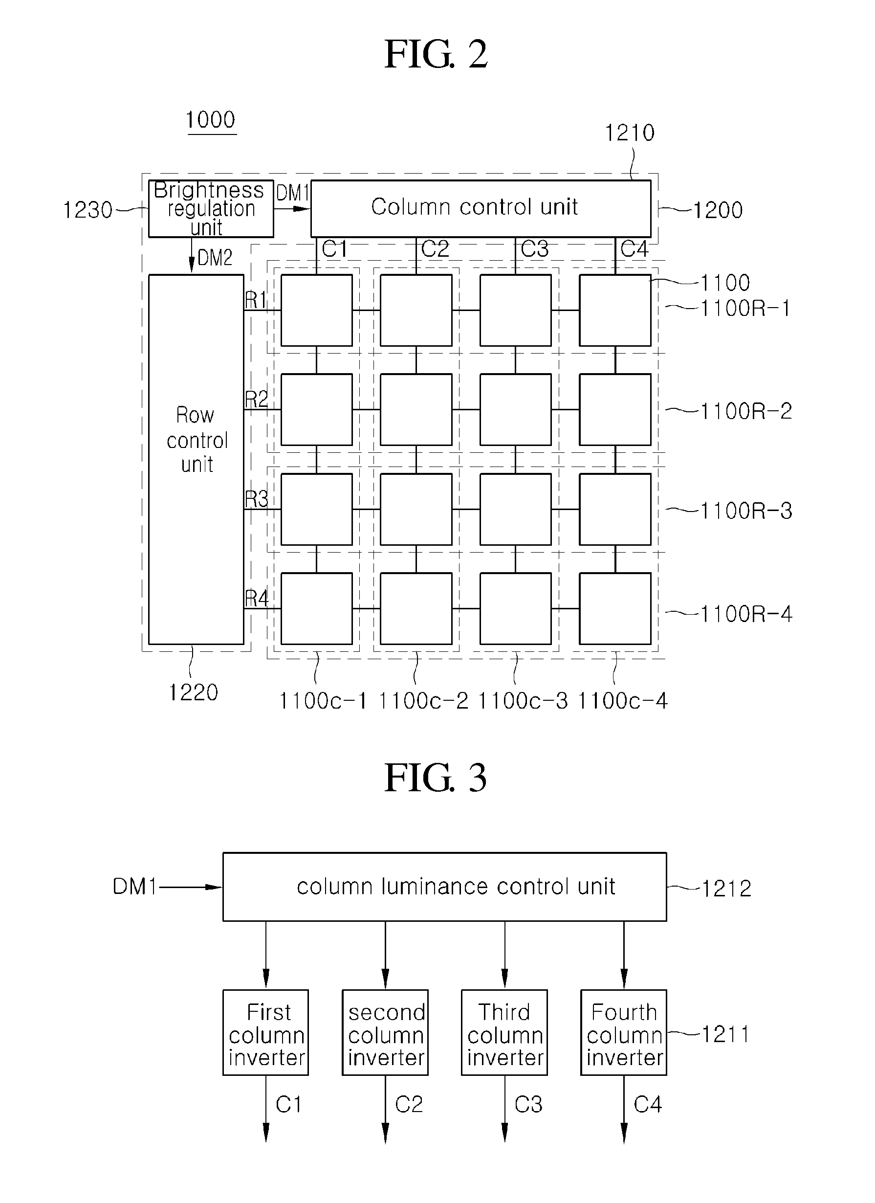
A light source module includes a plurality of light source units arranged in a matrix form and independently emitting light, and a light source control unit. The light source control unit includes a column control unit supplying a column control signal to a plurality of light source unit columns according to a brightness signal, a row control unit supplying a row control signal to a plurality of light source unit rows according to the brightness signal, and a brightness regulation unit supplying the brightness control signal to the column control unit and the row control unit. The plurality of light source units successively emit light for one frame in a light source column direction or a light source row direction, according to the brightness signal, the column control signal and the row control signal.

Description

[0001]This application claims the benefit of priority to Korean Patent Application No. 10-2007-0127509 filed on Dec. 10, 2007, and all the benefits accruing therefrom under 35 U.S.C. §119, the contents of which are incorporated by reference in their entirety.BACKGROUND OF THE INVENTION[0002]1. Field of the Invention[0003]The present invention relates to a light source module and a display device having the same, and more particularly, to a light source module including a plurality of light source units arranged in a matrix form, independently emit light according to the brightness of a screen corresponding to the light source units, and successively emit light in a row or column direction for one frame, respectively, whereby power consumption can be reduced.[0004]2. Description of the Related Art[0005]A liquid crystal display (“LCD”) panel, which is a flat display panel, is not a light emitting device but a light receiving device. Therefore, the light receiving device such as the LC...

Claims


Application Information

Patent Timeline
Patent Type & Authority Applications(United States)
IPC IPC(8): G09G3/34G09G3/36
CPCG09G3/342G09G2320/0646G09G2320/0626G02F1/133
Inventor KIM, HYUK-HWANCHO, CHI-OKIM, SEON-BAENAM, SEOK-HYUN
Owner SAMSUNG ELECTRONICS CO LTD
Learn More