Data input device and method for detecting an off-surface condition by a laser speckle size characteristic

a data input device and laser speckle technology, applied in the field of computer input devices, can solve problems such as inability to track on any surface, ball rotation, inaccurate or intermittent cursor tracking,

Inactive Publication Date: 2007-05-22
MICROSOFT TECH LICENSING LLC
View PDF40 Cites 37 Cited by
  • Summary
  • Abstract
  • Description
  • Claims
  • Application Information

AI Technical Summary

Problems solved by technology

Because such devices have a moving ball passing through a hole in the housing, such devices may become contaminated with dust and dirt, yielding inaccurate or intermittent cursor tracking.
Moreover, the tracking surface and ball require sufficient friction between the two to cause the ball to rotate when the housing translates over the surface.
Thus, a major limitation of such a device is that it requires a tracking surface with particular characteristics, such as adequate friction and cleanliness, which are not readily found on all surfaces that would otherwise be useful for tracking.
However, such devices lack the ability to track on any surface, requiring a suitable frictional interface between the ball and the surface.
Moreover, these devices still require one moving part, namely, the ball.
Moreover, such devices may become contaminated with dust and dirt, thereby possibly obscuring the detected pattern and / or creating fixed pattern noise on the detected image.
Finally, aliasing artifacts may also cause the cursor to skip, rather than move fluidly.
Although such devices are able to eliminate the moving ball, they are less universal by requiring a specific tracking surface to operate.
However, smooth surfaces with little color variation, such as surfaces with a fine microfinish similar to glass or clear plastic, may prove difficult to track upon.
Instead, they utilize focused optics and are thus inherently unable to track if the device has been lifted a significant distance from the tracking surface.

Method used


Image

  • Data input device and method for detecting an off-surface condition by a laser speckle size characteristic
  • Data input device and method for detecting an off-surface condition by a laser speckle size characteristic
  • Data input device and method for detecting an off-surface condition by a laser speckle size characteristic

Examples


Embodiment Construction

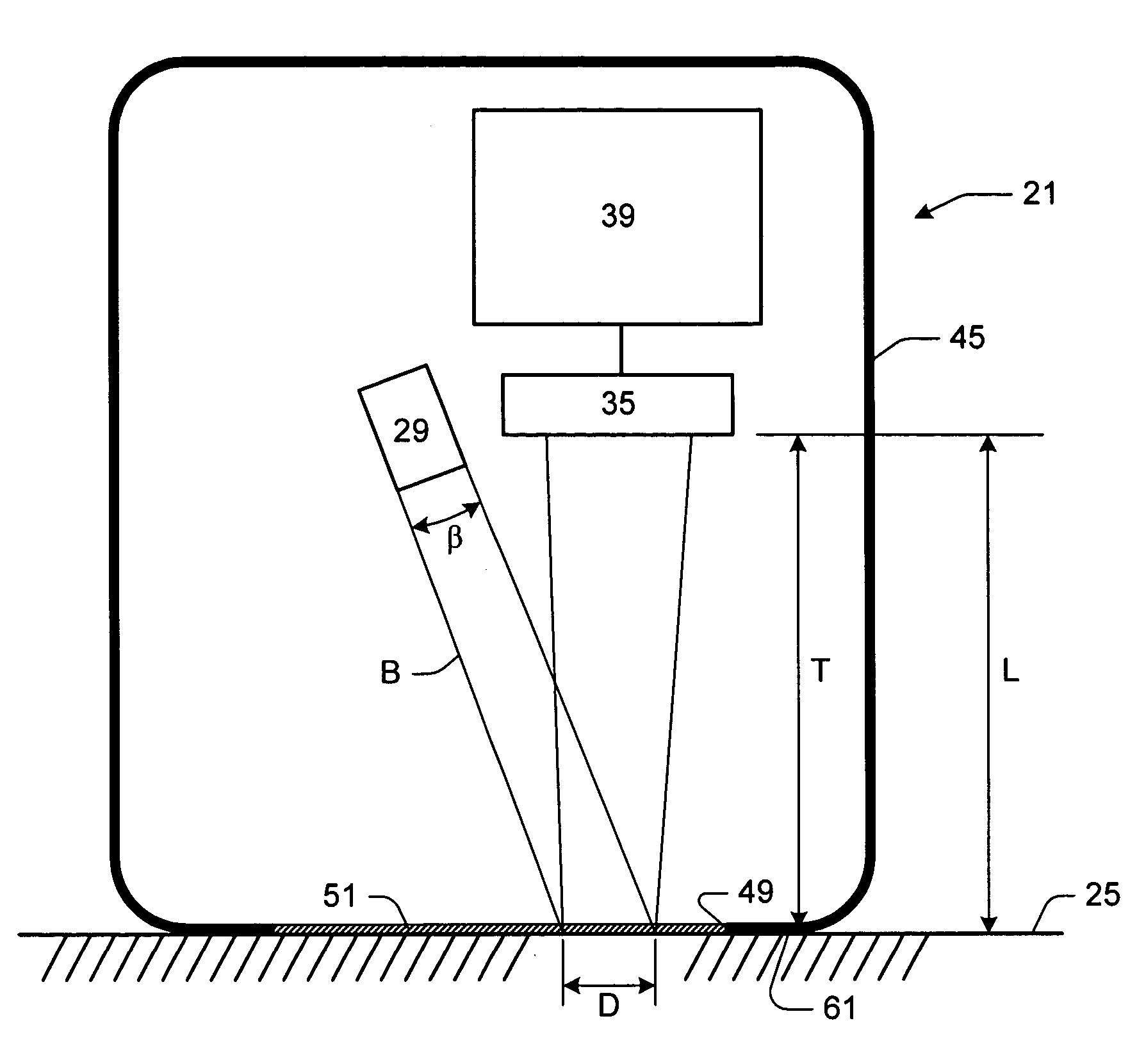
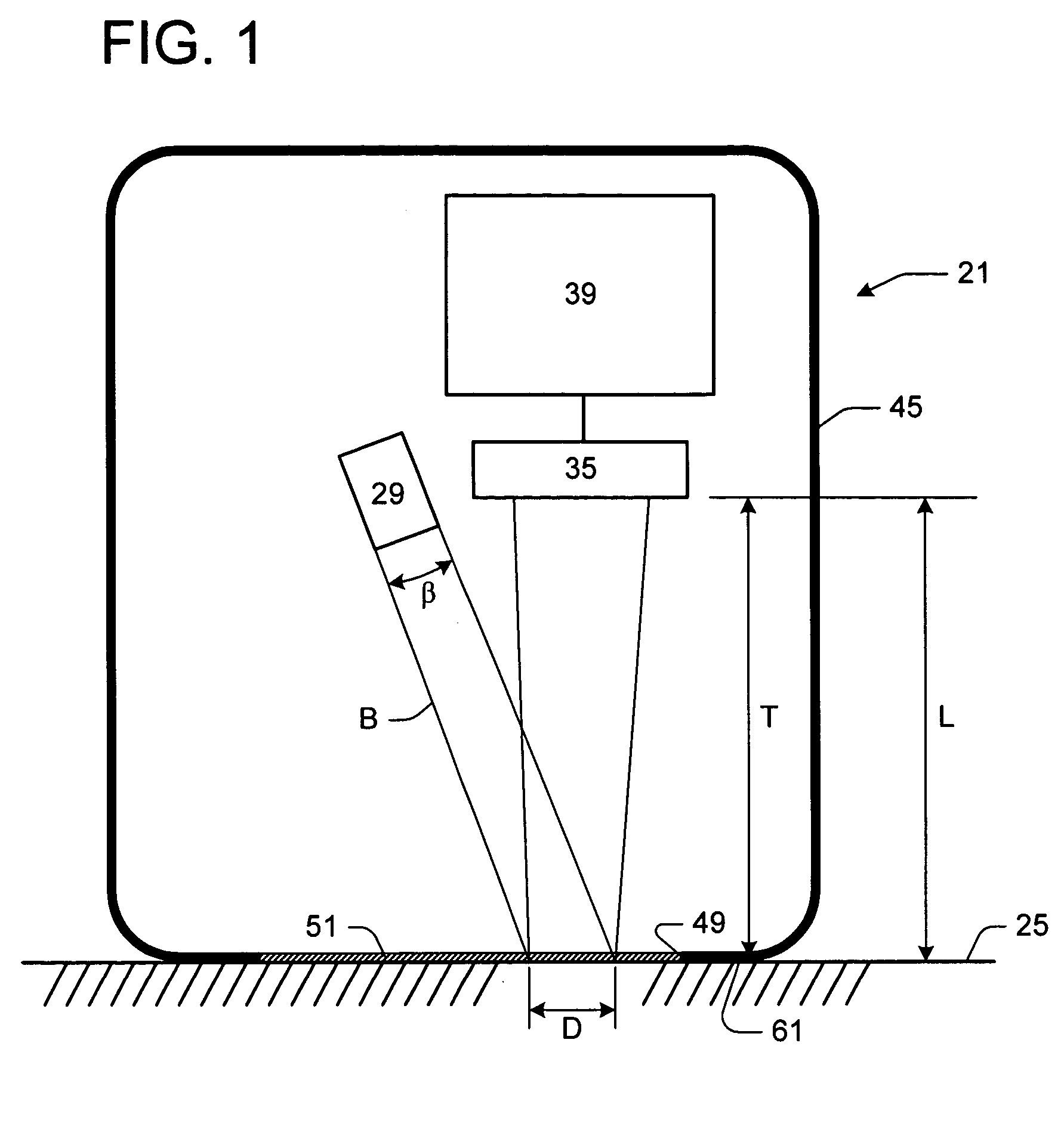
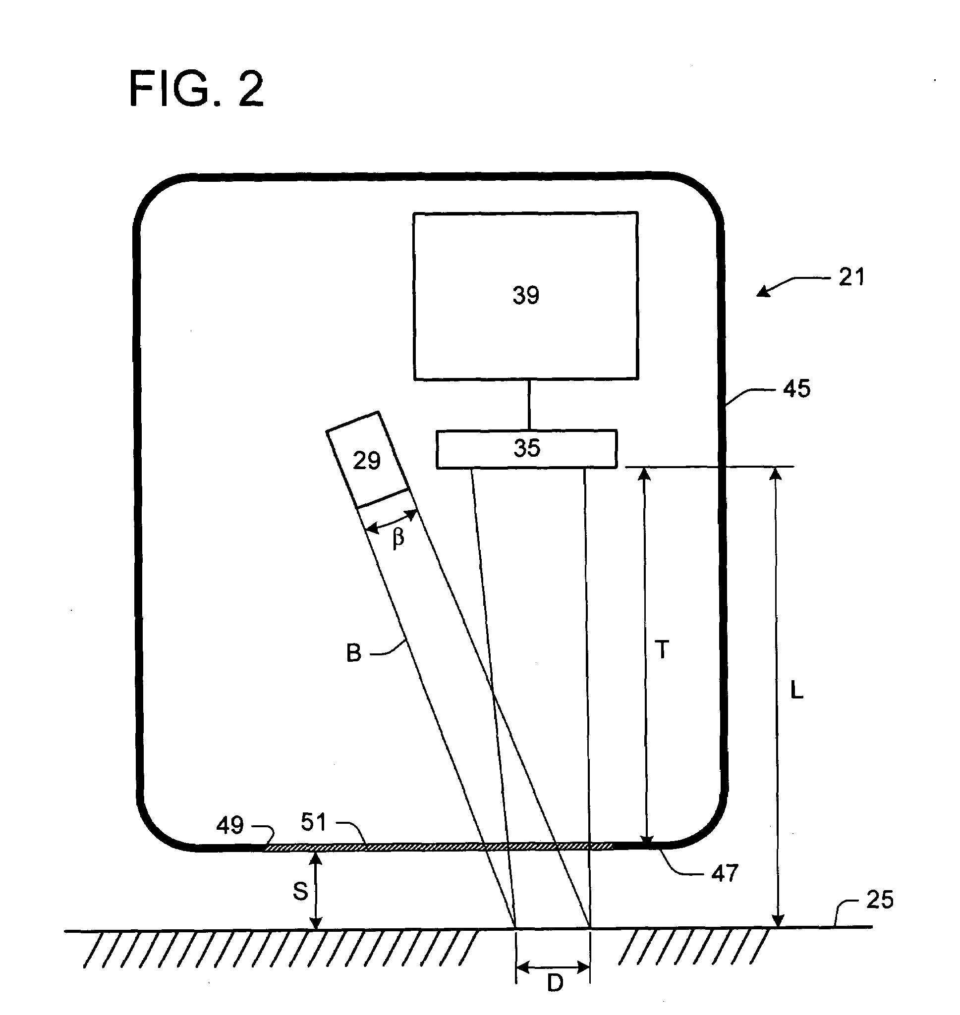
[0030]Referring first to FIGS. 1 and 2, a data input device, generally indicated 21, for use with a tracking surface 25 is depicted. Although such a device 21 is typically capable of tracking relative movement between the device and the tracking surface 25 (described above as horizontal-vertical movement or x-y movement), it should be noted here that a focus of the present disclosure specifically involves detection of an off-surface condition. Any of the various tracking schemes known in the relevant art may be coupled with the teaching of the present invention for lift-off detection. It should be noted here that the terms “lift-off”, “off-surface condition” or “lifting” the device 21 additionally comprise either lifting, or moving, the tracking surface 25 away from the stationary device (e.g., FIG. 4C), or lifting the device away from the tracking surface (e.g., FIGS. 2 and 4). In addition, referring to relative movement between the device 21 and the tracking surface 25 in a z-dire...


PUM


Abstract

A data input device for use with a tracking surface having light-scattering properties with respect to the device is disclosed. The device comprises a coherent light source for projecting a coherent light beam onto the tracking surface. The tracking surface scatters the coherent light beam striking the tracking surface. The device further comprises a detector associated with the coherent light source for detecting at least a portion of the scattered light. The detected portion of the scattered light comprising a speckle pattern. The device further comprises a controller configured to respond to the detected speckle pattern and operate the device in one of a tracking mode and a non-tracking mode, depending upon a speckle size characteristic of the detected speckle pattern as determined by the controller.

Description

TECHNICAL FIELD[0001]Embodiments of the present invention relate to the field of computer input devices, and particularly data input devices, such as a mouse or an optical pen, employing light striking a tracking surface for detecting movement. In particular, embodiments of this invention relate to data input devices capable of projecting a coherent light beam onto the tracking surface to scatter the coherent light beam, detecting at least a portion of the scattered light, the detected portion comprising a speckle pattern, and operating the device in one of a tracking mode and a non-tracking mode depending upon a speckle size characteristic of the detected speckle pattern.BACKGROUND OF THE INVENTION[0002]Previous computer input devices, such as mice, include rotatable balls mounted within a housing, yet rotatably engaging a surface. As the housing of such a mechanical mouse translates across the surface, the ball rotates within the housing, engaging horizontally and vertically situa...

Claims


Application Information

Patent Timeline
Patent Type & Authority Patents(United States)
IPC IPC(8): G09G5/00G01B11/00G06F3/033G06F3/038G06F3/042
CPCG06F3/0421G06F3/0304G06F3/038G06F3/03543G06F3/03547G06F3/0317G06F3/042
Inventor OLIVER, THOMAS C.POPE, JEREMIAH M.
Owner MICROSOFT TECH LICENSING LLC
Why Eureka
Try Eureka