
Printing system and program therefor

a printing system and printing technology, applied in the field of printing systems, can solve the problems of ink droplets not being produced at the intended droplet, clogging of nozzles, and increasing the viscosity of ink in the nozzles,

Inactive Publication Date: 2005-10-20
BROTHER KOGYO KK
View PDF7 Cites 3 Cited by
  • Summary
  • Abstract
  • Description
  • Claims
  • Application Information

AI Technical Summary

Benefits of technology

The present invention provides a printing system that can create images without needing a larger printer as the number of nozzles increases. The system includes a host computer and a printer that communicate with each other. The printer has a recording head with multiple nozzles that can eject ink droplets onto a recording medium. The host computer generates print data that is sent to the printer. The printer then generates a drive signal to activate the recording head based on the print data. The system also includes a pixel group generating unit that generates data related to pixels within the image forming range of the recording medium. This data includes information about pixels that are not ejected with ink droplets. The system uses this data to generate the drive signal for the recording head. Overall, the invention allows for efficient and precise printing without the need for larger printers.

Problems solved by technology

However, when ink droplets are not ejected from certain nozzles for a certain period of time, the nozzles become dry, increasing the viscosity of the ink in the nozzles.
When this happens, there is a danger that the nozzles will become clogged or that, even if the nozzles do not become clogged, that the next ink droplet ejected from the nozzles will not be produced at the intended droplet size.
Hence, a large number of counters is necessary for high-resolution printers provided with a large number of nozzles, resulting in a larger construction of the printer itself as the number of counters grows.

Method used


Image

  • Printing system and program therefor
  • Printing system and program therefor
  • Printing system and program therefor

Examples


Embodiment Construction

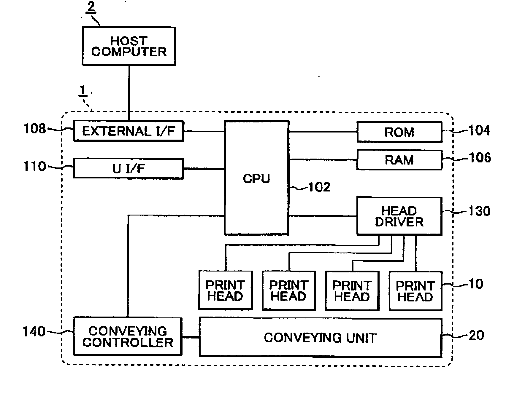
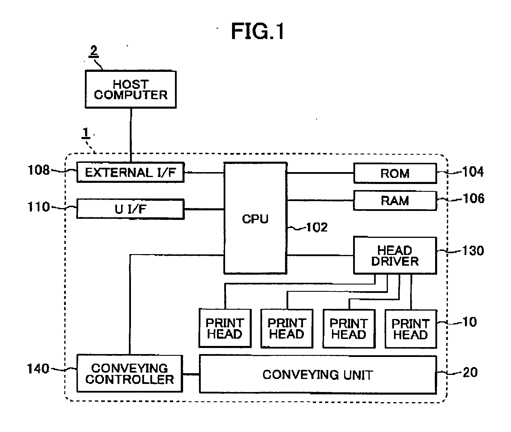
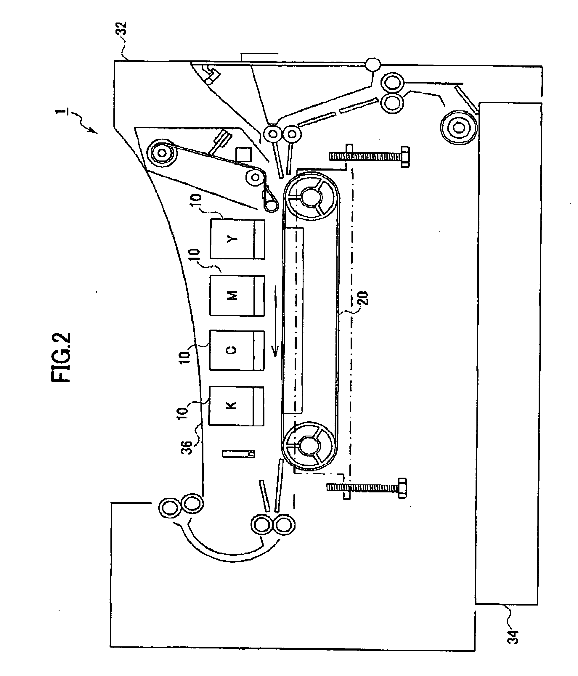
[0023] A printing system according to a preferred embodiment of the present invention will be described while referring to the accompanying drawings. Referring to FIG. 1, the printing system includes a printer 1, and a host computer 2 that is connected to and capable of performing data communications with the printer 1. FIG. 2 shows a basic internal structure of the printer 1.

[0024] As shown in FIG. 2, the printer 1 is a line head type color inkjet printer and includes four print heads 10 capable of ejecting ink droplets of different colors, a conveying unit 20 for conveying a recording paper so as to pass beneath the print head 10 and along a nozzle surface thereof, a casing 32 in which the print heads 10 and conveying unit 20 are accommodated, a paper tray 34 disposed in the bottom section of the casing 32, and a discharge tray 36 provided on the top of the casing 32.

[0025] The print heads 10 are provided one for each color of ink. In the preferred embodiment, the printer 1 has ...


PUM


Abstract

A printing system includes a host computer and a printer. The host computer generates pixel group data for a plurality of pixel groups as print data. The pixel group data is generated in a time series by processing pixel groups aligned in a paper conveying direction within an image foaming range. This data provides information for driving specific nozzles in each print head. The pixel group data also identifies non-ejection times indicating the number of times in the pixel group that ink droplets are not ejected from nozzles in succession. By considering the non-ejection times identified in this pixel group data to be “information for driving the nozzles,” the printer itself need not count nor identify the number of non-ejection times, but can drive the nozzles with drive waveforms corresponding to the number of non-ejection times.

Description

BACKGROUND OF THE INVENTION [0001] 1. Field of the Invention [0002] The present invention relates to a printing system including a printer and a host computer, and a computer program that is used in the printing system. [0003] 2. Description of the Related Art [0004] Conventional inkjet printers include a print head having a plurality of nozzles and form images by ejecting ink droplets from these nozzles. However, when ink droplets are not ejected from certain nozzles for a certain period of time, the nozzles become dry, increasing the viscosity of the ink in the nozzles. When this happens, there is a danger that the nozzles will become clogged or that, even if the nozzles do not become clogged, that the next ink droplet ejected from the nozzles will not be produced at the intended droplet size. [0005] Various technologies have been proposed to resolve these issues. Japanese unexamined patent application publication 11-314360 discloses a print head driving circuit including a counte...

Claims


Application Information

Patent Timeline
Patent Type & Authority Applications(United States)
IPC IPC(8): B41J2/01B41J2/05B41J2/21B41J29/38G06F3/12G06K15/10
CPCG06K15/1814G06K15/102
Inventor TOBITA, MANABU
Owner BROTHER KOGYO KK
Learn More