
Tape drive sensor system

a sensor system and tape drive technology, applied in the field of tape drive sensor system, can solve the problems of increasing and achieve the effect of reducing the cost and complexity of the driv

Inactive Publication Date: 2005-10-20
QUANTUM CORP
View PDF6 Cites 6 Cited by
  • Summary
  • Abstract
  • Description
  • Claims
  • Application Information

AI Technical Summary

Problems solved by technology

Unfortunately, as the number of sensors utilized in a given drive increases, the cost and complexity of the drive typically increases as well.

Method used


Image

  • Tape drive sensor system
  • Tape drive sensor system
  • Tape drive sensor system

Examples


Embodiment Construction

[0015] In the following description, reference is made to the accompanying drawings which illustrate several embodiments of the present invention. It is understood that other embodiments may be utilized and mechanical, compositional, structural, electrical, and operational changes may be made without departing from the spirit and scope of the present disclosure. The following detailed description is not to be taken in a limiting sense, and the scope of the embodiments of the present invention is defined only by the claims of the issued patent.

[0016] Some portions of the detailed description which follows are presented in terms of procedures, steps, logic blocks, processing, and other symbolic representations of operations on data bits that can be performed on computer memory. A procedure, computer executed step, logic block, process, etc., are here conceived to be a self-consistent sequence of steps or instructions leading to a desired result. The steps are those utilizing physical...


PUM


Abstract

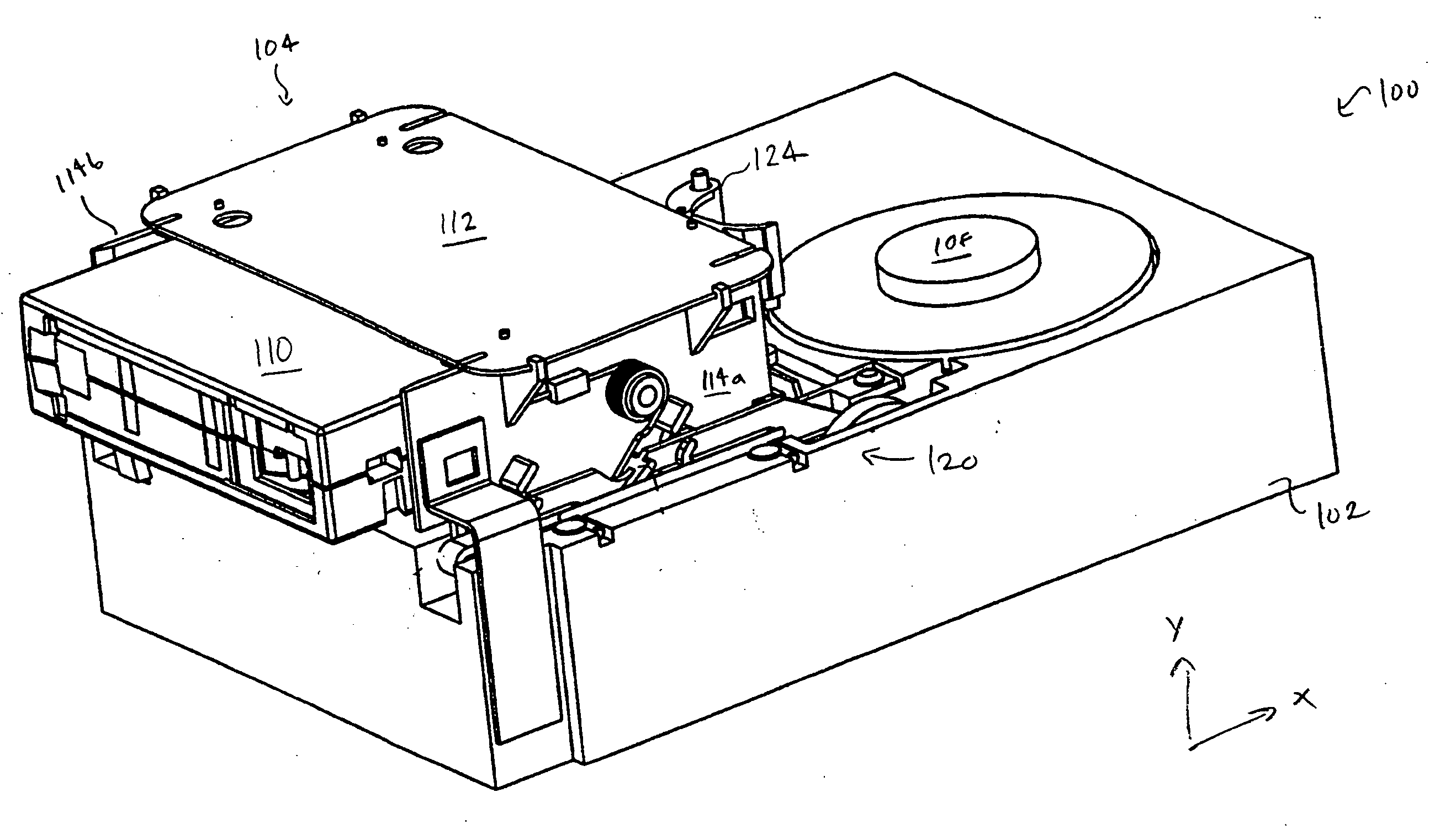
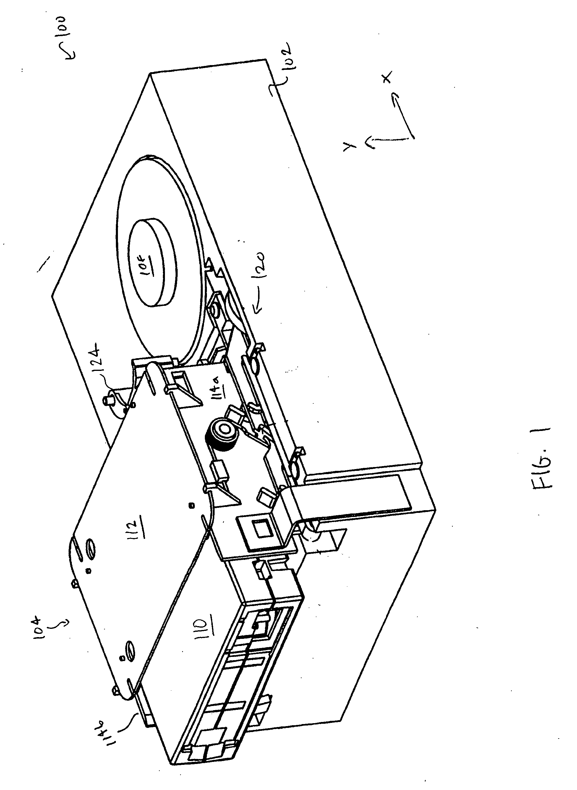
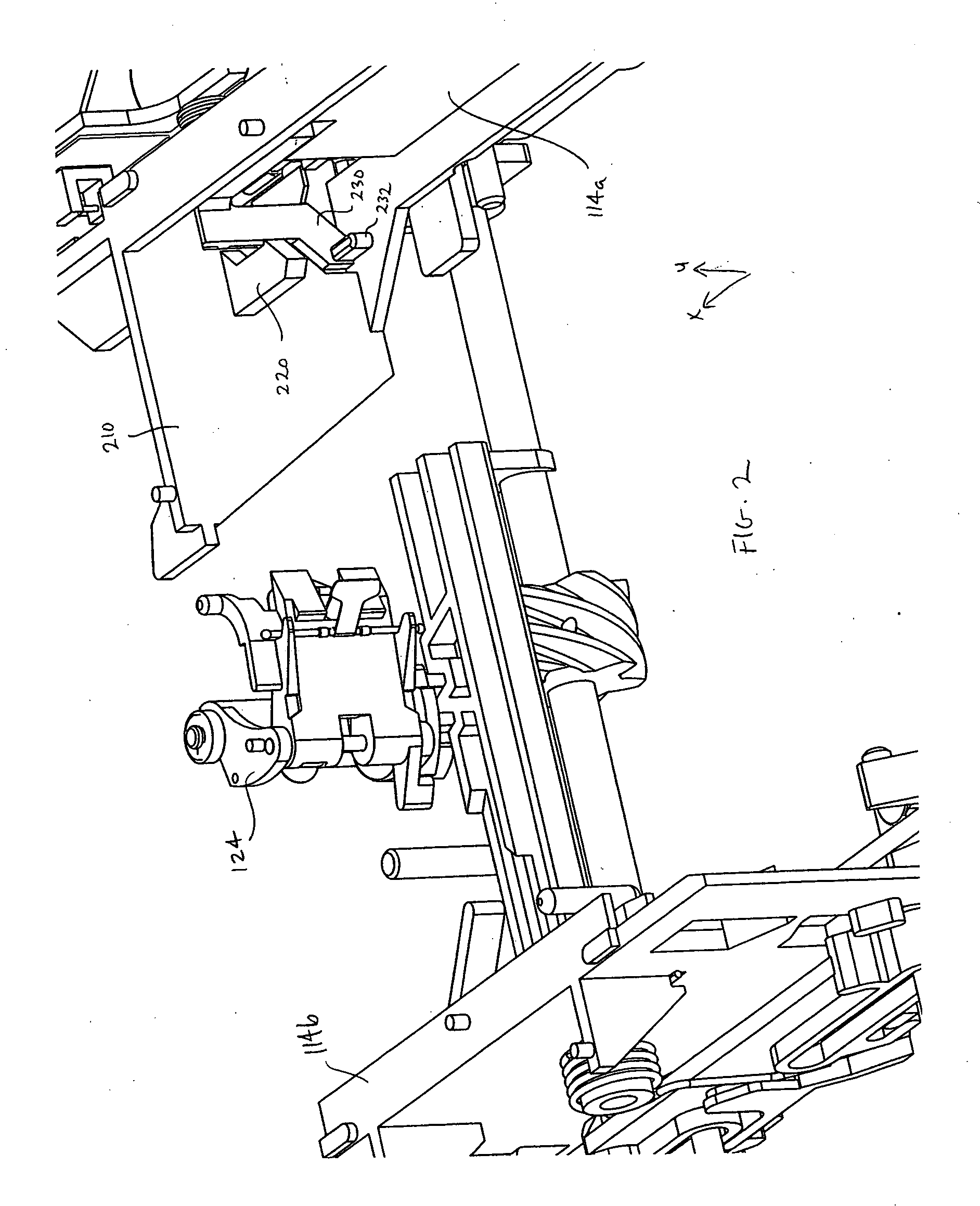
Data drives and methods of operating a data drive are described. The drive includes: a drive base; a receiver for receiving a storage media device, the receiver being movably coupled to the drive base and translatable from an unloaded position to a loaded position; a media flag movably coupled to the receiver and translatable from a first position to a second position when the storage media device is inserted into the receiver; a media flag sensor fixedly coupled to the drive base for detecting movement of the receiver flag; a receiver flag fixedly coupled to the receiver; and a receiver flag sensor fixedly coupled to the drive base for detecting movement of the receiver flag. The method includes: receiving a storage media device into a receiver such that the storage media device contacts a media flag movably coupled to the receiver; detecting movement of the media flag using a media flag sensor; actuating movement of the receiver from an unloaded position to a loaded position; and detecting movement of a receiver flag fixedly coupled to the receiver using a receiver flag sensor.

Description

BACKGROUND OF THE INVENTION [0001] Storage subsystems, such as magnetic tape libraries, are widely used for storing information in digital form. These tape subsystems may include a storage subsystem controller for controlling one or more tape drives contained within the storage subsystem and for controlling other components of the storage subsystem, such as the tape picker, which is used to select and load tape cartridges into the tape drives. The storage subsystem may be coupled to a host system which transmits I / O requests to the storage subsystem via a host / storage connection. [0002] Each tape drive reads and writes data to the primary storage medium, which can be, for example, a magnetic tape medium contained within a removable storage media device, such as, e.g., a removable magnetic tape cartridge or cassette. The magnetic tape medium typically comprises a thin film of magnetic material which stores the data. The tape medium may be moved by the tape drive between a pair of spa...

Claims


Application Information

Patent Timeline
IPC IPC(8): G11B15/00G11B15/07G11B15/675G11B23/04
CPCG11B15/07G11B23/042G11B15/67555
Inventor RATHWEG, CHRISTOPHERSTAMM, STEPHEN J.
Owner QUANTUM CORP
Learn More