Bio-information measuring apparatus

Inactive Publication Date: 2005-10-20
KK TOSHIBA
View PDF2 Cites 144 Cited by
  • Summary
  • Abstract
  • Description
  • Claims
  • Application Information

AI Technical Summary

Benefits of technology

[0017] It is an object of the present invention to at l

Problems solved by technology

Therefore, it is not assumed that a conventional bio-information measuring apparatus is used for a long time and if the user wears it for a long time, the user has a strong pain.
In the medical field, a sensor capable of being worn for a long time is also used, however, wearing of this type is very troublesome because the sensor head is needed to be fixed by an adhesive plaster or the like.
However, if the autonomic state and a sleeping state are transmitted for each time of measurement in the bio-information measuring apparatus, electric power consumption is increased and a battery is remarkably burn.
Upon these reasons, the above-described ring type apparatus involves a problem such that the operations from attachment to measurement cannot be easily carried out.
The belt type apparatus disclosed in Japanese Patent Application Laid-Open No. 2001-224561 serv

Method used


Image

  • Bio-information measuring apparatus
  • Bio-information measuring apparatus
  • Bio-information measuring apparatus

Examples


first embodiment

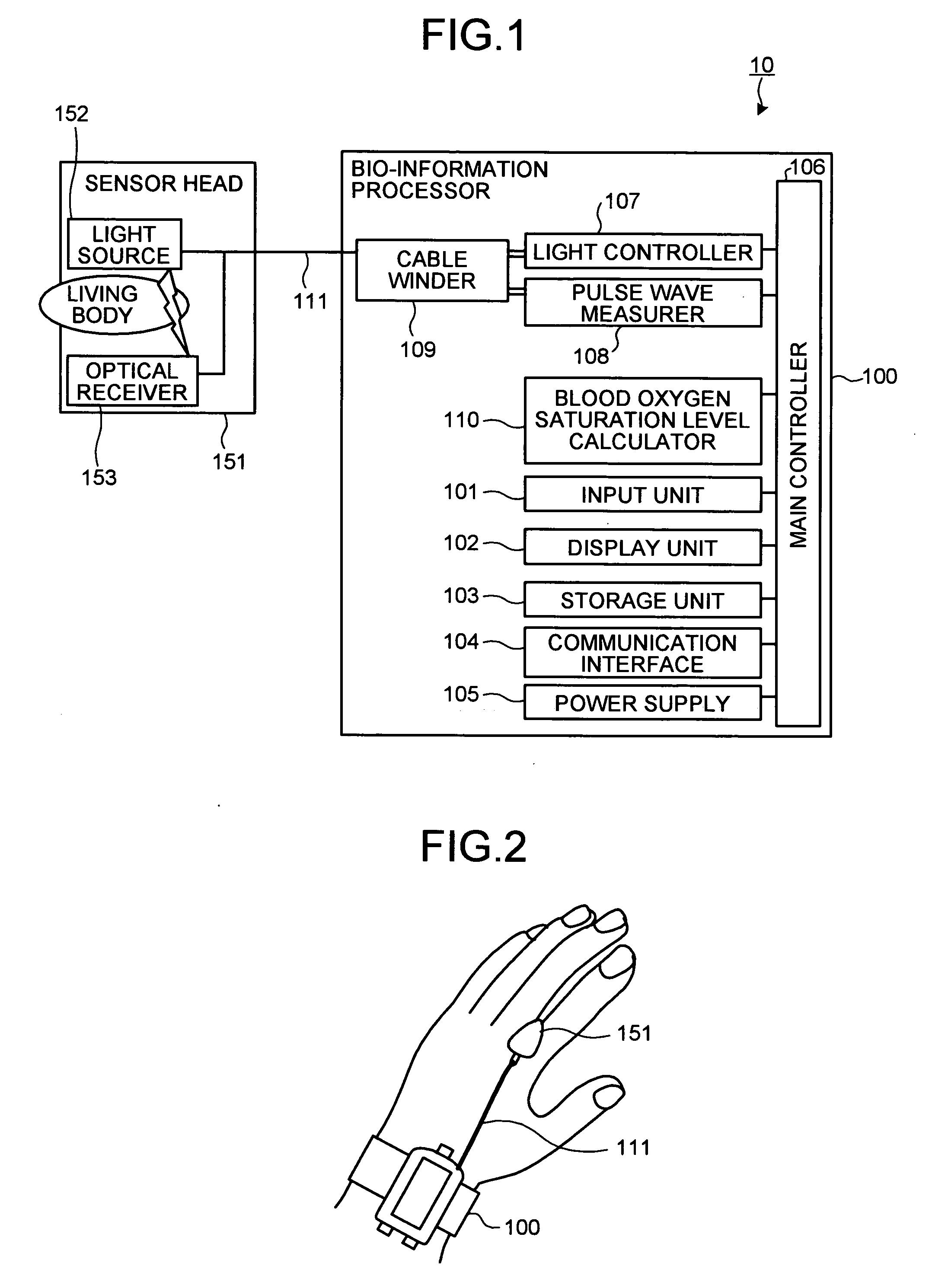
[0062]FIG. 1 is a block diagram that depicts a configuration of a bio-information measuring apparatus according to the present invention. As shown in FIG. 1, the bio-information measuring apparatus 10 has a bio-information processor 100 and a sensor head 151 that is connected to the bio-information processor 100 via a cable 111. In addition, the bio-information measuring apparatus 10 has an input unit 101, a display unit 102, a storage unit 103, a communication interface 104, a power supply 105, a main controller 106, a light controller 107, a pulse wave measurer 108, a cable winder 109, and a blood oxygen saturation level calculator 110.

[0063] When the examinee wears the bio-information measuring apparatus 10, it is possible to measure the bio-information of the examinee. FIG. 2 shows a state that the examinee wears the bio-information measuring apparatus 10 according to the first embodiment. In FIG. 2, the examinee puts the sensor head 151 between his or her fingers and the bio-in...

second embodiment

[0108]FIG. 30 is a block diagram of the bio-information measuring apparatus according to the In FIG. 30, the same reference numerals are given to the portions same as FIG. 1 and their explanations are herein omitted. A bio-information processor 200 shown in FIG. 30 is not provided with the cable winder, and a sensor head 151 is directly connected to the light source controller 107 and the pulse wave measurer 108 of the bio-information processor 200.

[0109] A cable 120 is located elastically in a longitudinal direction and includes a signal line therein. FIG. 31 shows an example of the cable 120. In FIG. 31, a signal line 112 is sealed in the tube 113 of a helix structure like a cable of a telephone receiver. According to this example, particularly, the tube 113 is preferably formed by a material with a higher hardness than that of a normal receiver cable in order to secure the tension.

[0110]FIG. 32 shows other example of the cable 120. In FIG. 32, the signal line 112 is embedded in...

third embodiment

[0113] The pulse wave sensor 302 is a pulse wave sensor of a reflection type and is configured by a red diode and a photo diode and the pulse wave sensor 302 serves to convert amount of blood from the reflection of a red diode emission into an electric signal in the photo diode. The pulse wave sensor 302 is needed to be attached to a portion where the pulse wave can be measured, for example, a tip of a finger of the user. However, a portion where the pulse wave sensor 302 is attached is not limited to the tip of the finger of the user.

[0114] The acceleration sensor 301 is means that is worn by the user to measure the body motion, and for example, the acceleration sensor 301 is a three-axes acceleration sensor. In the meantime, the acceleration sensor 301 may be provided separately from the bio-information measuring apparatus 300 because kinds and accuracy of the obtained information are changed depending on a selected portion where the user wears the acceleration sensor 301.

[0115]...


PUM


Abstract

A bio-information measuring includes a detector including a light source emitting light to a hand of an examinee and an optical receiver receiving the light emitted from the light source; and a supporter bent to clamp a paddle between fingers of the examinee. The clamping portion of the supporter is provided with the detector. The bio-information measuring apparatus also includes a measurer worn on the examinee, measuring bio-information based on pulse wave data obtained from the optical receiver; and a puller pulling the support member toward the measurer.

Description

CROSS-REFERENCE TO RELATED APPLICATIONS [0001] This application is based upon and claims the benefit of priority from Japanese Patent Applications No. 2004-101318 and No. 2004-101319, both filed Mar. 30, 2004; and Japanese Patent Application No. 2005-001850, filed Jan. 6, 2005, the entire contents of both of which are incorporated herein by reference. BACKGROUND OF THE INVENTION [0002] 1) Field of the Invention [0003] The present invention relates to a bio-information measuring apparatus that serves to measure the bio-information of a user on the basis of a pulse wave between the user's fingers or the like, and particularly, the present invention relates to a configuration of the apparatus and an art to set a condition for performing communication on the basis of the measured bio-information. [0004] 2) Description of the Related Art [0005] A pulse wave can be measured by irradiating a finger or an ear lobe of an examinee with light and then detecting reflected light or transmitted l...

Claims


Application Information

Patent Timeline
IPC IPC(8): A61B5/0245A61B5/00A61B5/103A61B5/145A61B5/1455A61B5/16G09B3/00
CPCA61B5/103A61B5/14551A61B5/14552A61B5/4806A61B2562/222A61B5/681A61B5/6826A61B5/6838A61B5/6825A61B5/4809
Inventor SUZUKI, TAKUJIKAMEYAMA, KENICHIMORIYA, AKIHISAOUCHI, KAZUSHIGE
Owner KK TOSHIBA
Why Eureka
Try Eureka