Low power and personal pulse oximetry systems

a pulse oximetry and low power technology, applied in the field of pulse oximetry, can solve the problems of increasing the difficulty of other consumer applications of pulse oximetry, the impracticality of tying soldiers, patients or athletes to external pulse oximeters, and the inability to use board level products on their own, so as to reduce the cost of repair and replacement.

Inactive Publication Date: 2005-10-20
MASIMO CORP
View PDF99 Cites 345 Cited by
  • Summary
  • Abstract
  • Description
  • Claims
  • Application Information

AI Technical Summary

Benefits of technology

The invention describes a small device that measures blood flow through pulses without requiring a connection to another device. This makes it more convenient and comfortable for individuals to use. It also has built-in wireless capabilities compatible with various healthcare, military, and social networks. Additionally, this device offers easier maintenance, lower cost, user identity verification, and other similar features.

Problems solved by technology

The technical problem addressed in this patent is the limitations of conventional pulse oximetry systems due to the bulky equipment required (including the sensor and monitor), high cost, and limited application scenarios. These restrictions make it challenging to utilize pulse oximetry in areas such as medicine, sport, and personal wellness. This patent seeks to provide solutions to improve the portability and practicality of pulse oximetry technology.

Method used


Image

  • Low power and personal pulse oximetry systems
  • Low power and personal pulse oximetry systems
  • Low power and personal pulse oximetry systems

Examples


Embodiment Construction

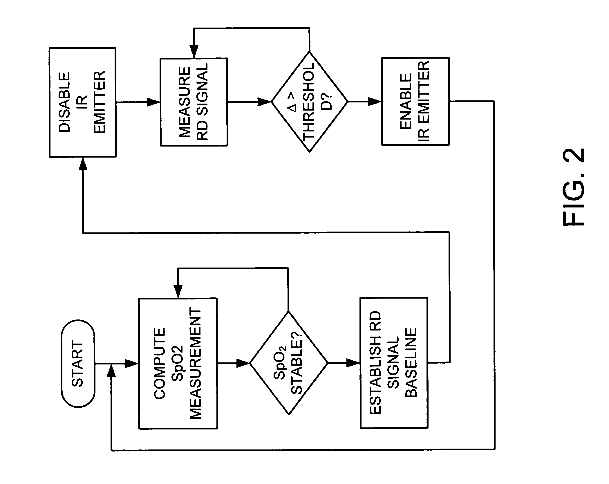
[0029]FIGS. 2-3 illustrate an exemplary low power pulse oximetry process. During a first time period T1 (FIG. 3), both RD (red) and IR (infrared) emitters are enabled and SpO2 measurements are computed and displayed. If the SpO2 measurements are stable, i.e. the values do not change more than a predetermined amount during a predetermined time interval, then a RD signal baseline is established. The baseline may be, for example, an average of the AC component of the RD signal. The IR emitter is then disabled during a second time period T2 (FIG. 3). In an embodiment, the RD signal is periodically measured and compared to the baseline value. If the absolute difference (Δ) is greater than a predetermined threshold, then the IR emitter is re-enabled. During this third time period T3 (FIG. 3), SpO2 measurements are once again computed. Although a low power pulse oximetry process is described above with respect to enabling and disabling an IR emitter and periodically measuring a RD emitter,...


PUM


Abstract

Personal pulse oximetry systems and methods are disclosed which provide monitoring, powering, and wireless communications for measurement of an individual's blood oxygen levels in medical, military, or athletic applications. In an embodiment, at least one intensity signals is disabled so as to reduce power consumption.

Description


Claims


Application Information

Patent Timeline
Owner MASIMO CORP
Why Eureka
Try Eureka