Cryogenic probehead cooler in a nuclear magnetic resonance apparatus

a nuclear magnetic resonance and probehead cooler technology, applied in the field of nuclear magnetic resonance apparatuses, can solve the problems of correspondingly halving up time until the next refilling action, and achieve the effects of reducing the energy requirements for liquefaction, less cooling energy, and minimizing thermal losses

Active Publication Date: 2012-09-27
BRUKER SWITZERLAND AG
View PDF34 Cites 27 Cited by
  • Summary
  • Abstract
  • Description
  • Claims
  • Application Information

AI Technical Summary

Benefits of technology

[0036]In one particularly preferred embodiment, a cryo-cooling finger projects into a chamber that is connected to the nitrogen tank of the cryostat. A combination of the inventive device and a cryo-cooling finger enables continuous operation of cryostat and probehead. A cryo-cooling finger is used for generating a cold surface on which nitrogen gas can condense. Refilling of the nitrogen tank, which is otherwise always necessary and is extremely inconvenient, is no longer necessary.
[0037]One advantageous further development of this embodiment is characterized in that the chamber containing the cryo-cooling finger is connected to an external gas supply. The cryostat is permanently refilled due to condensation of the gas from the external gas supply, and complex return of the cold gas is not required.
[0038]One particularly preferred embodiment of the invention is characterized in that a waste gas line is provided for returning the nitrogen gas, which leaves the NMR probe head, into a chamber that is connected to the nitrogen tank of the cryostat. This provides a closed loop and a virtually loss-free cryostat as we

Problems solved by technology

The proposed inventive solution may seem to be disadvantageous at first glance, since one would initially assume that this would, roughly estimated, double

Method used


Image

  • Cryogenic probehead cooler in a nuclear magnetic resonance apparatus
  • Cryogenic probehead cooler in a nuclear magnetic resonance apparatus
  • Cryogenic probehead cooler in a nuclear magnetic resonance apparatus

Examples


Embodiment Construction

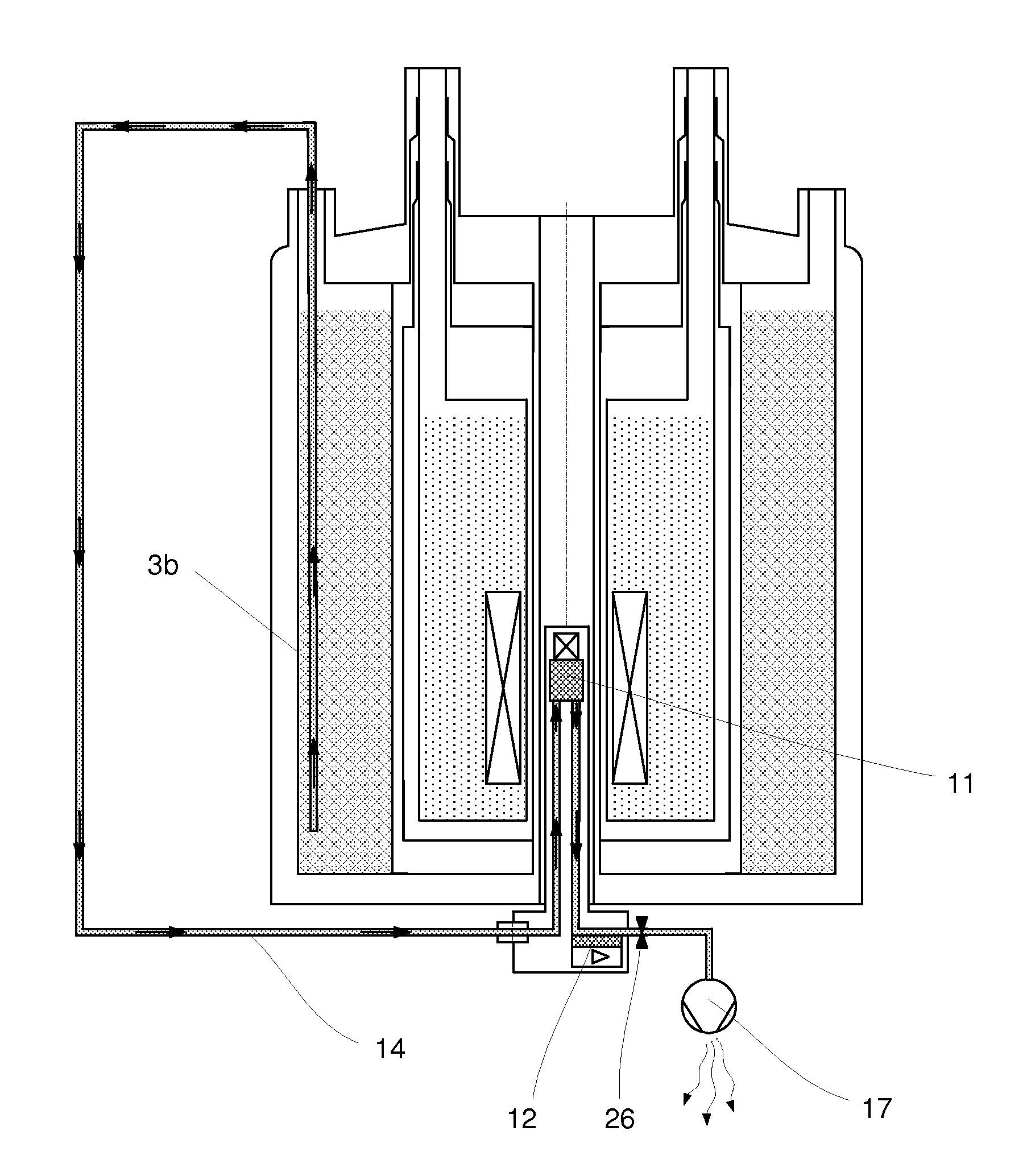
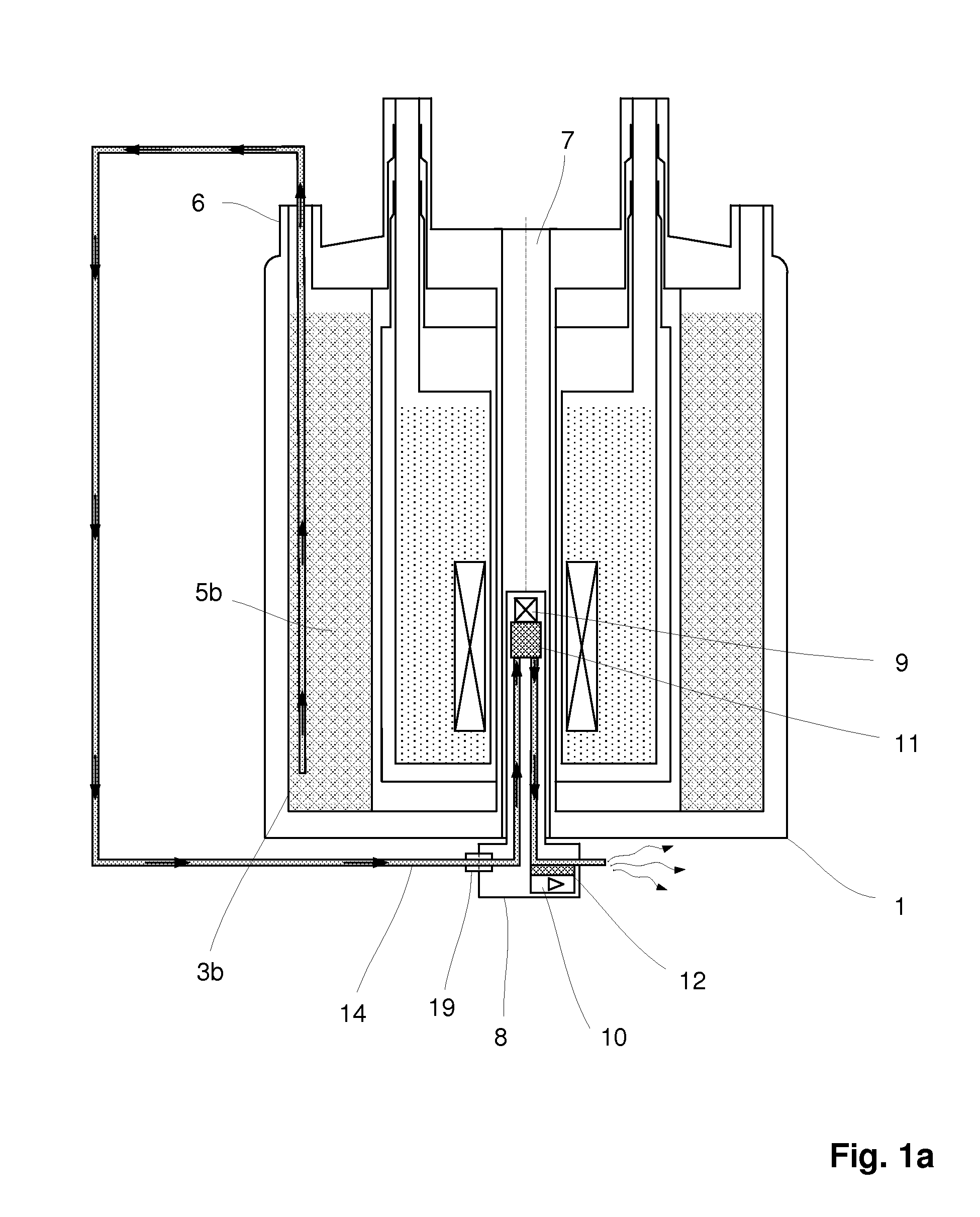
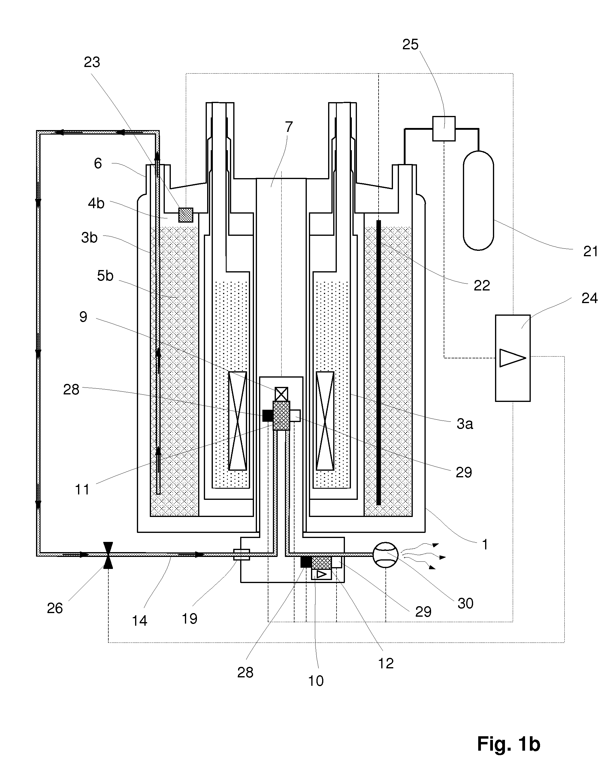
[0052]For cooling the transmitting and receiving system in the probehead, consisting of RF part and preamplifier, nitrogen is removed from the nitrogen tank of the cryostat via a supply line.

[0053]The end of the supply line on the cryostat side is immersed into liquid nitrogen in the tank.

[0054]The end of the supply line on the probehead side is coupled to the probehead by means of a separable connection and is in continuous connection with the heat exchangers in the probehead for cooling the transmitting and receiving system.

[0055]The supply line, which is ideally vacuum-insulated, is installed on a nitrogen evaporation tower and thereby connected to the nitrogen tank of the cryostat.

[0056]The invention can be used both for cryostats with a horizontally and also vertically aligned room temperature bore.

[0057]Nitrogen is guided into the probehead, where it discharges heat, which is generated in the probehead through RF power and preamplifier electronics, via one or more heat exchang...


PUM


Abstract

An NMR (nuclear magnetic resonance) apparatus has a magnet system disposed in a cryostat (1), the cryostat having at least one nitrogen tank (3b) for receiving liquid nitrogen (5b) and a room temperature bore (7) for receiving an NMR probehead (8), wherein part(s) of the probehead or the overall probehead can be cooled to cryogenic temperatures by supplying liquid nitrogen (5b) via a supply line (14). The nitrogen tank (3b) of the cryostat (1) is connected to the NMR probehead (8) by means of a supply line (14) in such a fashion that liquid nitrogen (5b) is removed from the nitrogen tank (3b) and guided to the NMR probehead (8). The overall apparatus is therefore more compact, the operating comfort of the apparatus is increased, and the costs for acquisition, operation and maintenance are considerably reduced compared to previous comparable devices.

Description

[0001]This application claims Paris Convention priority of DE 10 2011 005 888.5 filed Mar. 22, 2011 the complete disclosure of which is hereby incorporated by reference.BACKGROUND OF THE INVENTION[0002]The invention concerns an NMR (nuclear magnetic resonance) apparatus comprising a magnet system that is arranged in a cryostat, the cryostat having at least one nitrogen tank for receiving liquid nitrogen, and a room temperature bore for receiving an NMR probehead with a transmitting and receiving system, wherein part(s) of the probehead or the overall probehead can be cooled to cryogenic temperatures by supplying liquid nitrogen via a supply line.[0003]An NMR apparatus of this type, comprising a cryostat and a cooled NMR probehead is disclosed e.g. in U.S. Pat. No. 5,247,256 (document [1]).[0004]FIG. 2 schematically shows the prior art described in [1].[0005]A cryostat 1 contains an inner tank 3a with gaseous helium 4a and liquid helium 5a for cooling a superconducting magnet coil 2,...

Claims


Application Information

Patent Timeline
IPC IPC(8): G01R33/31
CPCG01R33/3403
Inventor SCHETT, OSKARBAUMANN, DANIEL GUYSCHNELL, MARCCETREFLI, CENGIZMAREK, DANIELKESSLER, KLEMENSSTAUFFENEGGER, PHILIPPE
Owner BRUKER SWITZERLAND AG
Why Eureka
Try Eureka