Vertebral body placeholder

a placeholder and vertebral body technology, applied in the field of vertebral body spacers, can solve the problems of difficult to bring the two cylinders into the side, the desired size of the spacer is difficult to adjust, and the side is difficult to bring the two cylinders into the spacer, so as to achieve the effect of convenient and reliable adjustmen

Inactive Publication Date: 2005-10-20
METZ STAVENHAGEN PETER
View PDF4 Cites 56 Cited by
  • Summary
  • Abstract
  • Description
  • Claims
  • Application Information

AI Technical Summary

Benefits of technology

[0008] In view thereof, it is the object of the present invention to provide a vertebral bod

Problems solved by technology

For the operating surgeon it is however very tedious to adjust the desired size of the vertebral body spacer and to then insert said screw into the corresponding thread, particularly because the outer and the inner body are very likely to become displaced with respect to one another and because it needs a certain dexterity to insert the fixation

Method used


Image

  • Vertebral body placeholder
  • Vertebral body placeholder
  • Vertebral body placeholder

Examples


Embodiment Construction

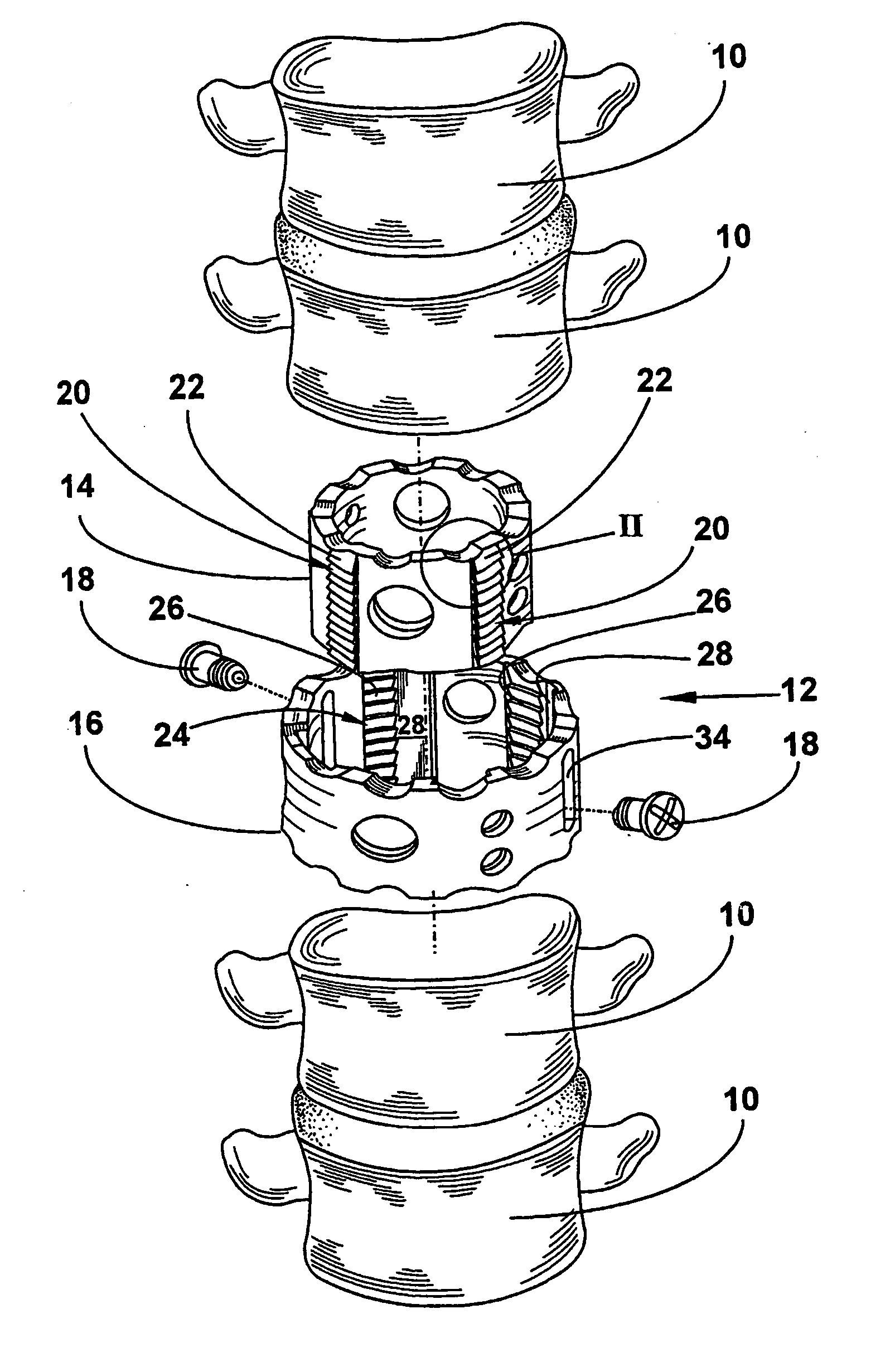
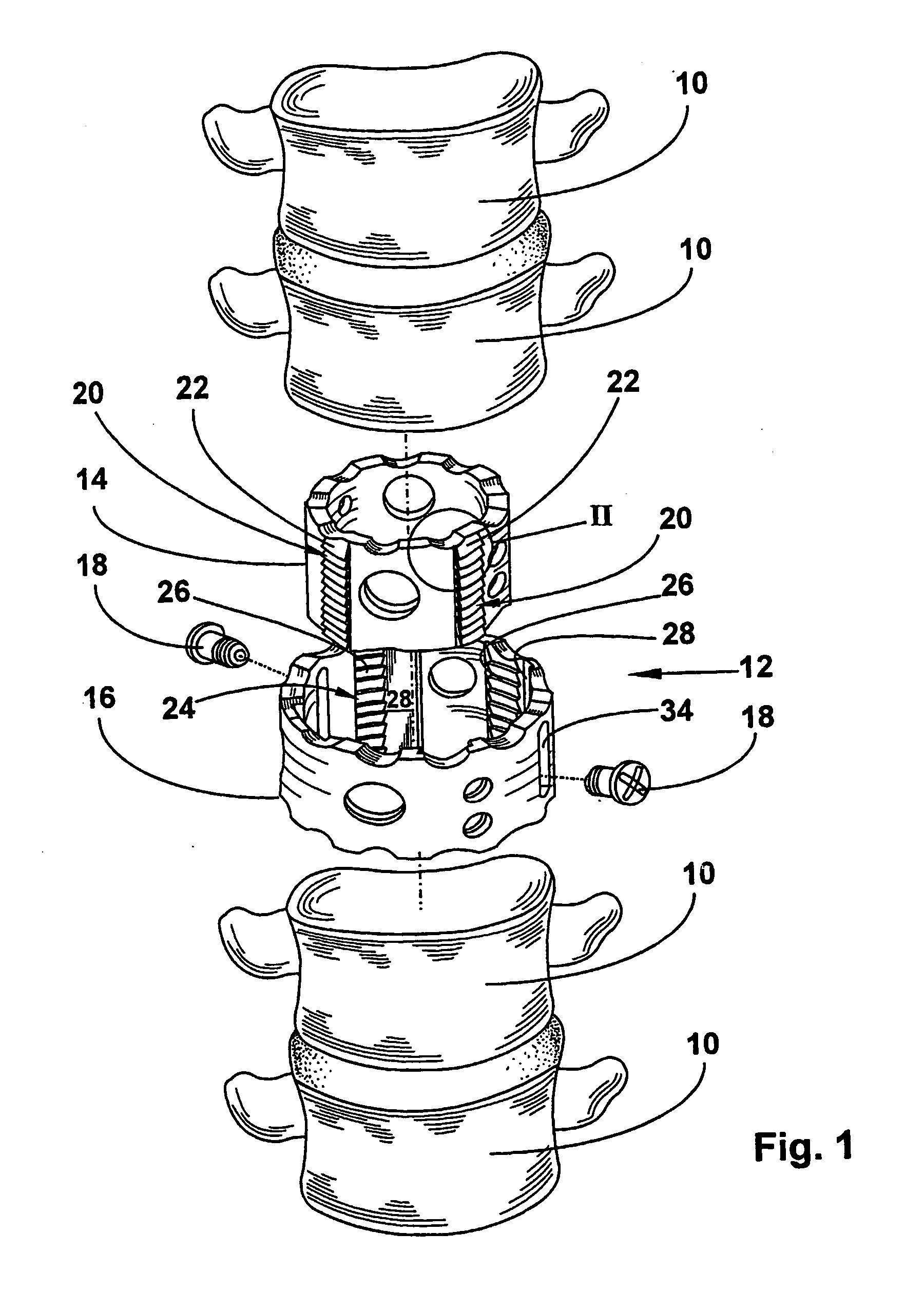
[0021]FIG. 1 is an exploded schematic partial view of a human spine in which there is arranged, between two vertebral bodies 10, a bipartite, cylindrical hollow spacer 12 for a vertebral body. Said spacer 12 is comprised of a smaller, cylindrical inner body 14 and of a larger, sleeve-like outer body 16 which is also cylindrical and positively and telescopically receives the inner body 14. In an effort to achieve an optimal position of the spine, the operating surgeon may fix inner body 14 and outer body 16 in the desired relative position using two fixation screws 18. A long hole 34 arranged in the outer body 16 permits to fix the spacer 12 in any position. For further details relating to spacer 12 the reader is referred to German Patent DE 296 16 778 / European Patent 832 622, the full content of which is incorporated herein by way of reference.

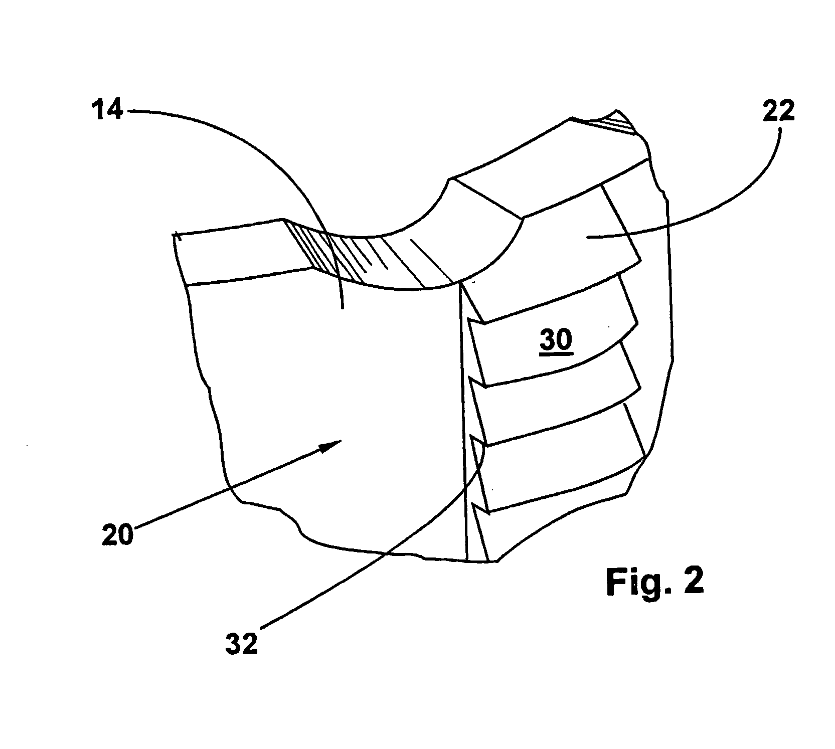
[0022] Four rows of detent lugs 20 are provided at regular intervals around the circumference of the outer side of inner body 14, said rows ...


PUM


Abstract

The invention relates to a vertebral body placeholder having a cylindrical inner body (14), which can be telescopically inserted into a coaxially arranged sleeve-shaped outer body (16). A detent device that works in one direction is arranged between the inner body (14) and the outer body (16). A number of detent projections (22) are arranged in succession in an axial direction and form a row (20) of detent projections. A number of detent notches (26) are arranged in succession in an axial direction while corresponding to the row (20) of detent projections. Said detent notches form a row (24) of detent notches that completely or partially accommodate the row (20) of detent projections. The invention also relates to a method for assembling said vertebral body placeholder. The aim of the invention is to create a vertebral body placeholder whose overall height can be easily and reliably adjusted, particularly, during implantation. To this end, a groove (28) for accommodating the row (20) of detent projections without obstructing it is provided next to the row (24) of detent notches.

Description

BACKGROUND OF THE INVENTION [0001] DE 202 07 853.1 dated May 21, 2002 [0002] 1. Field of the Invention [0003] The present invention relates to a vertebral body spacer according to the features of claim 1 and to a method of assembling the same. [0004] 2. Description of the Prior Art [0005] A vertebral body spacer having a cylindrical inner body that is telescopically slidable into a coaxially arranged, sleeve-shaped outer body is known from DE 296 16 778. In order to fix said vertebral body spacer in the desired position, it can be guided through the outer body into a thread embedded in the inner body. By arranging a plurality of holes and threads in the axial direction, the vertebral body spacer can be adjusted gradually. For the operating surgeon it is however very tedious to adjust the desired size of the vertebral body spacer and to then insert said screw into the corresponding thread, particularly because the outer and the inner body are very likely to become displaced with resp...

Claims


Application Information

Patent Timeline
IPC IPC(8): A61F2/00A61F2/30A61F2/44
CPCA61F2/44A61F2230/0069A61F2002/30235A61F2002/3024A61F2002/30367A61F2002/30373A61F2002/30433A61F2002/30489A61F2002/30507A61F2002/3054A61F2002/3055A61F2002/30551A61F2002/30601A61F2002/30774A61F2002/30777A61F2002/30785A61F2002/30787A61F2002/30818A61F2002/4475A61F2220/0025A61F2220/0033A61F2220/0041A61F2230/0006A61F2002/30115A61F2002/30487A61F2002/30593
Inventor METZ-STAVENHAGEN, PETER
Owner METZ STAVENHAGEN PETER
Why Eureka
Try Eureka