Valve timing controller

a timing controller and timing controller technology, applied in the direction of valve drives, machines/engines, output power, etc., can solve the problems of detecting the lower limit value, the generation of control signals using the control circuit and the electrical conducting operation of the motor using the driving circuit cannot be realized

Active Publication Date: 2005-10-27
DENSO CORP
View PDF1 Cites 10 Cited by
  • Summary
  • Abstract
  • Description
  • Claims
  • Application Information

AI Technical Summary

Benefits of technology

[0005] An object of the present invention is to provide a valve timing controller of the motor utilizing type able to suitably control the valve timing in accordance with the real rotation speed of the engine.
[0006] In accordance with the present invention, when the real rotation speed of the engine is less than a reference value, a control circuit generates a control signal on the basis of a motor rotation signal showing the real rotation speed or the real rotation position of the motor. Thus, even when the real rotation speed of the engine becomes a low rotation speed less than the reference value, the control signal is generated by the control circuit and an electric conducting operation of the motor according to this control signal can be realized by a driving circuit. When the real rotation speed of the engine becomes the reference value or more, the control circuit generates the control signal on the basis of an engine speed signal showing the real rotation speed of the engine. Thus, when the real rotation speed of the engine becomes a high rotation speed equal to or greater than the reference value, the generation of the control signal based on the engine speed signal and the electric conducting operation of the motor according to this control signal can be realized similarly to the conventional case. Accordingly, the valve timing can be appropriately adjusted in accordance with the real rotation speed of the engine.

Problems solved by technology

However, in the above controller, a detecting lower limit value inevitably exists in the rotation speed sensor of the engine.
Therefore, when the real rotation speed of the engine becomes a low rotation speed smaller than the detecting lower limit value, the generation of the control signal using the control circuit and the electrical conducting operation of the motor using the driving circuit cannot be realized.

Method used


Image

  • Valve timing controller
  • Valve timing controller
  • Valve timing controller

Examples


first embodiment

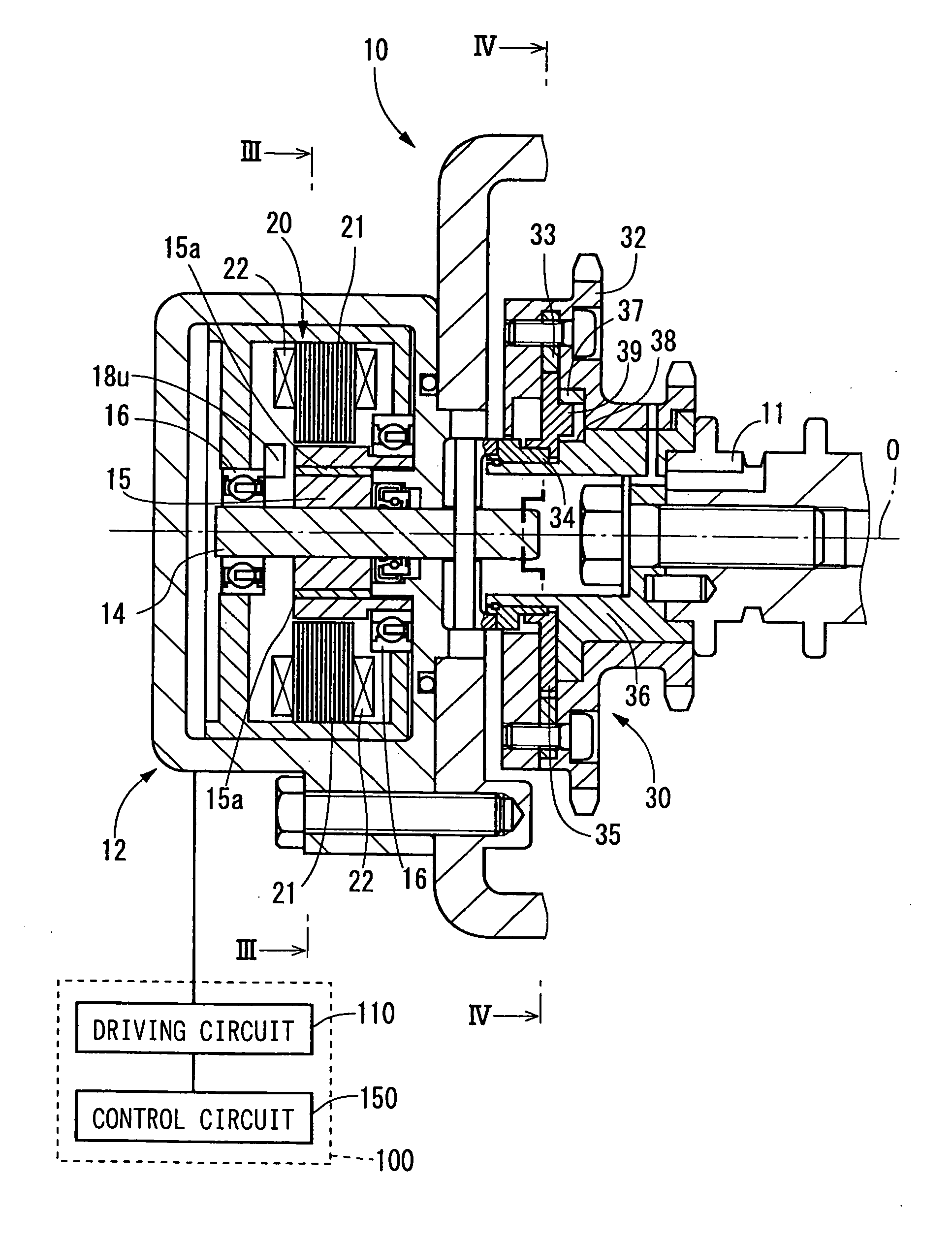
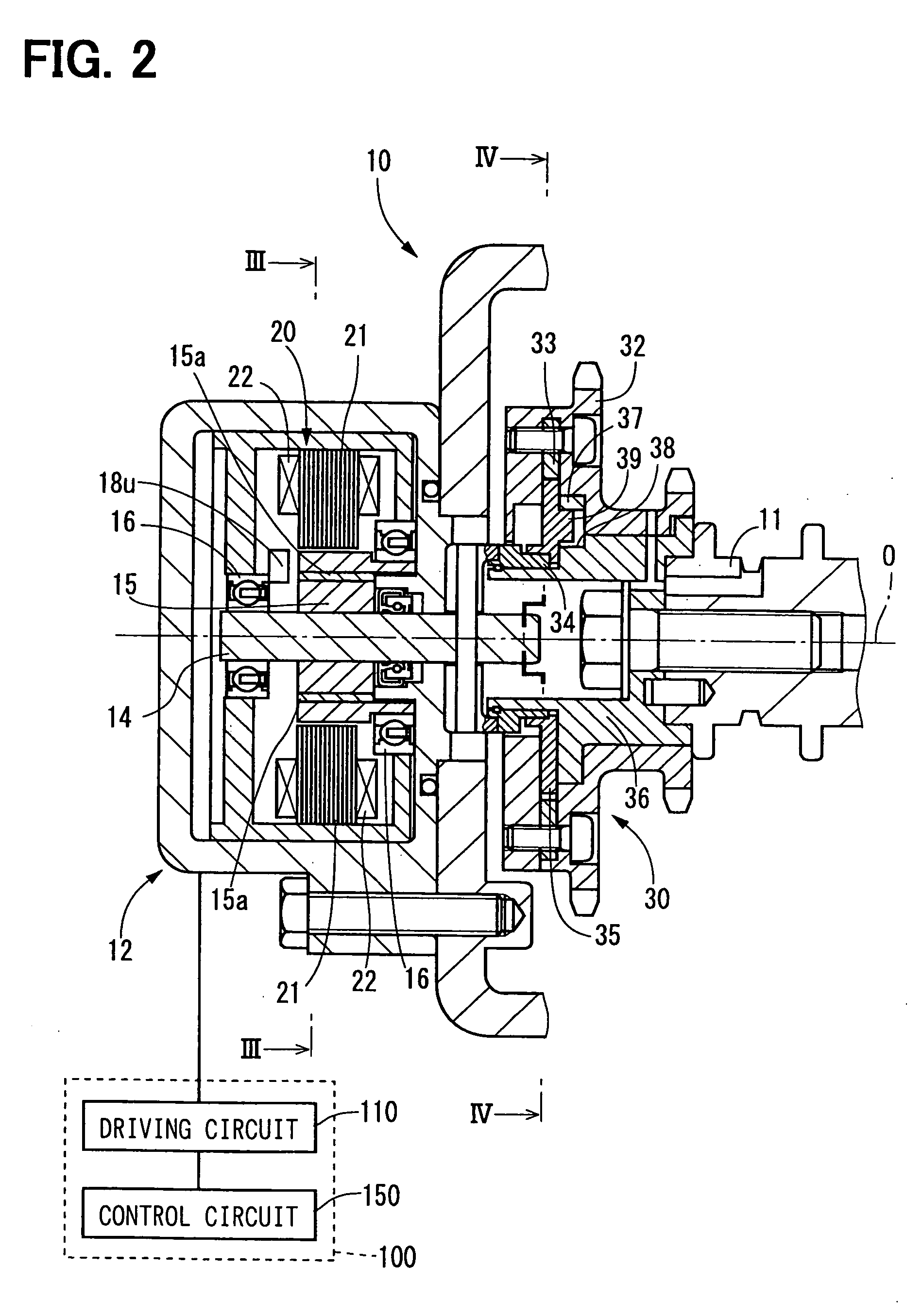
[0030] A valve timing controller in accordance with a first embodiment of the present invention is shown in FIGS. 2 to 4. The valve timing controller 10 additionally arranged in the engine of a vehicle adjusts valve timing with respect to an intake valve or an exhaust valve of the engine by utilizing the rotation torque of a motor 12.

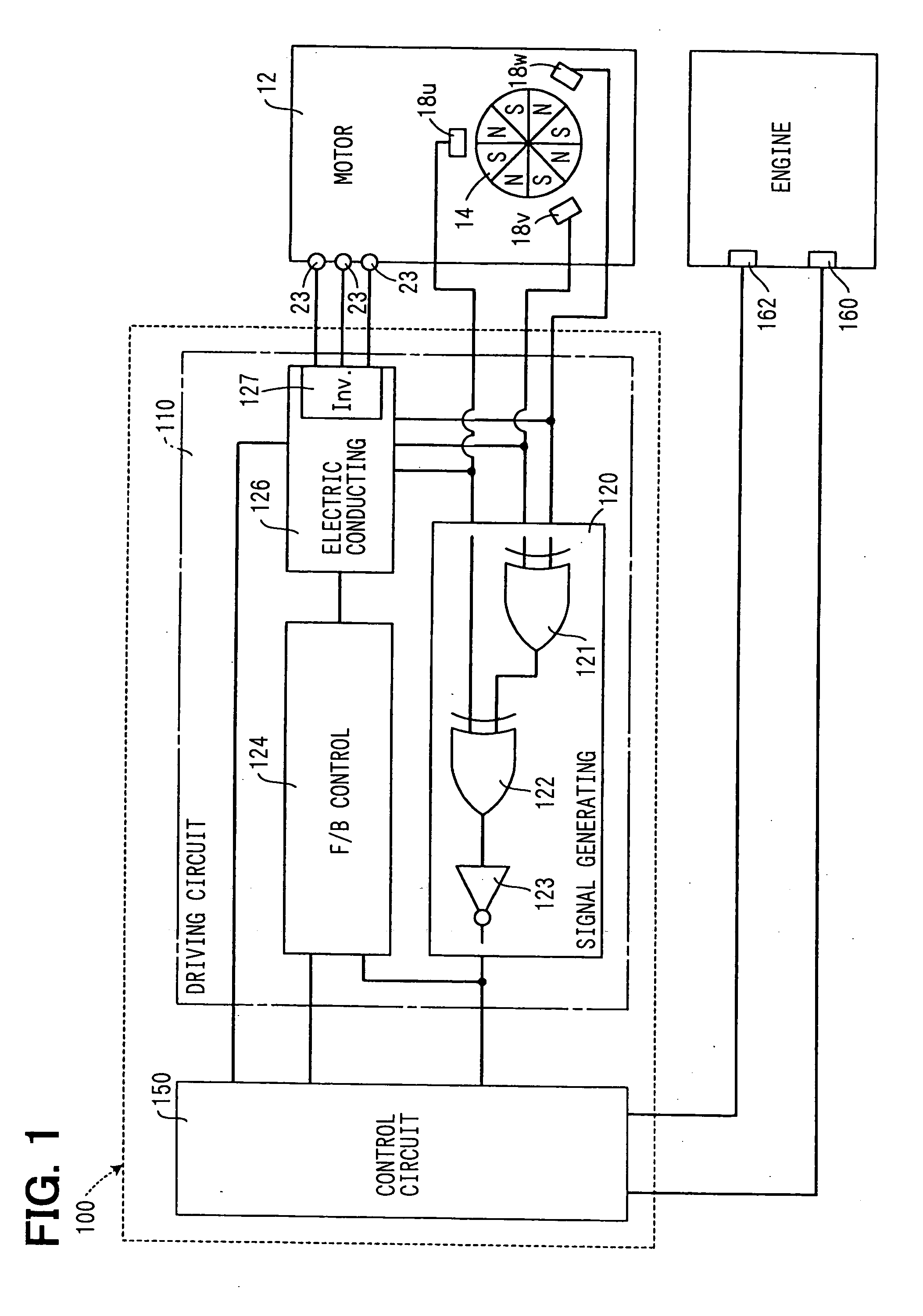
[0031] As shown in FIGS. 2 and 3, the motor 12 of the valve timing controller 10 is a three-phase brushless motor having a motor shaft 14, a bearing 16, Hall effect elements 18u, 18v, 18w as rotation position sensors, and a stator 20.

[0032] The motor shaft 14 is supported by two bearings 16 and can be rotated in the normal and reverse directions around the axis O. In this embodiment, the clockwise direction of FIG. 3 among the rotating directions of the motor shaft 14 is set to the normal rotating direction, and the counterclockwise direction of FIG. 3 is set to the reverse rotating direction. The motor shaft 14 forms a rotor portion 15 of a disk shap...

second embodiment

[0060] As shown in FIG. 8, a second embodiment of the present invention is a modified example of the first embodiment. The substantial same constructional portions as the first embodiment are designated by the same reference numerals, and their explanations are omitted.

[0061] A motor controller 200 of the second embodiment has a rotation signal generating circuit 210 corresponding to the rotation signal generating section 120 of the first embodiment as a circuit different from a driving circuit 220. In the motor controller 200 of such a second embodiment, effects similar to those in the case of the motor controller 100 of the first embodiment are also obtained.

third embodiment

[0062] As shown in FIG. 9, a third embodiment of the present invention is a modified example of the first embodiment, and the substantial same constructional portions as the first embodiment are designated by the same reference numerals and their explanations are omitted.

[0063] In a motor controller 250 of the third embodiment, a control circuit 260 is connected to Hall effect elements 18u, 18v, 18w through a driving circuit 270. The control circuit 260 receives a detecting signal generated by each of the Hall effect elements 18u, 18v, 18w as a motor rotation signal showing the real rotating position θ of the motor shaft 14. The control circuit 260 calculates the absolute value of the real rotation speed Rm of the motor shaft 14 by realizing a function similar to that of each of gates 121, 122, 123 of the rotation signal generating section 120 of the first embodiment, and also calculates the sign of the real rotation speed Rm similarly to the rotation signal generating section 120 ...


PUM


Abstract

A valve timing controller of a motor utilizing type has a control circuit for generating a control signal, and a driving circuit for turning-on and driving the motor in accordance with the control signal generated by the control circuit. The control circuit for receiving a motor rotation signal showing the real rotation speed of the motor, and an engine speed signal showing the real rotation speed of the engine generates the control signal on the basis of the motor rotation signal when the real rotation speed of the engine is less than a reference value. The control circuit also generates the control signal on the basis of the engine speed signal when the real rotation speed of the engine becomes the reference value or more.

Description

CROSS-REFERENCE TO RELATED APPLICATION [0001] This application is based on Japanese Patent Applications No. 2004-128259 filed on Apr. 23, 2004 and No. 2005-67415 filed on Mar. 10, 2005, the disclosure of which are incorporated herein by reference. FIELD OF THE INVENTION [0002] The present invention relates to a valve timing controller, which controls a valve timing of an intake valve and / or an exhaust valve of an internal combustion engine. BACKGROUND OF THE INVENTION [0003] JP-U-4-105906A shows a valve timing controller of an engine by utilizing a rotation torque of a motor. In the valve timing controller of such a motor utilizing type, a control signal is conventionally generated by a control circuit on the basis of an engine speed signal showing the real rotation speed of the engine, and the motor is electrically turned on and is driven by a driving circuit in accordance with this generated control signal. Here, a detecting signal of a rotation speed sensor for detecting the real...

Claims


Application Information

Patent Timeline
Patent Type & Authority Applications(United States)
IPC IPC(8): F01L1/352F01L1/34F01L13/00F02D13/02
CPCF01L1/352F01L1/34F01L2201/00
Inventor TANI, HIDEJI
Owner DENSO CORP
Why Eureka
Try Eureka