Transfer arrangement and method

a technology of transfer arrangement and transfer stroke rate, applied in the direction of metal-working feeding device, manufacturing tool, press, etc., can solve the problems of large and rugged, and achieve the effect of high press stroke rate and rapid activation

Inactive Publication Date: 2005-10-27
SCHULER PRESSEN GMBH & CO KG
View PDF4 Cites 6 Cited by
  • Summary
  • Abstract
  • Description
  • Claims
  • Application Information

AI Technical Summary

Benefits of technology

[0011] As a result, the carriage drive provides most of the power needed for the transfer of the workpieces. It can be large and rugged. Its weight is of no consideration since it is stationary. The pivot drives on the other hand do not need to be powerful so that the moving parts of the transfer arrangement, that is, the arms and the parts supported thereby can be very lightweight.
[0012] The transport arrangement described so far can move very rapidly because of the energetic and power-based optimization. If the workpiece support structur...

Problems solved by technology

It can be ...

Method used


Image

  • Transfer arrangement and method
  • Transfer arrangement and method
  • Transfer arrangement and method

Examples


Embodiment Construction

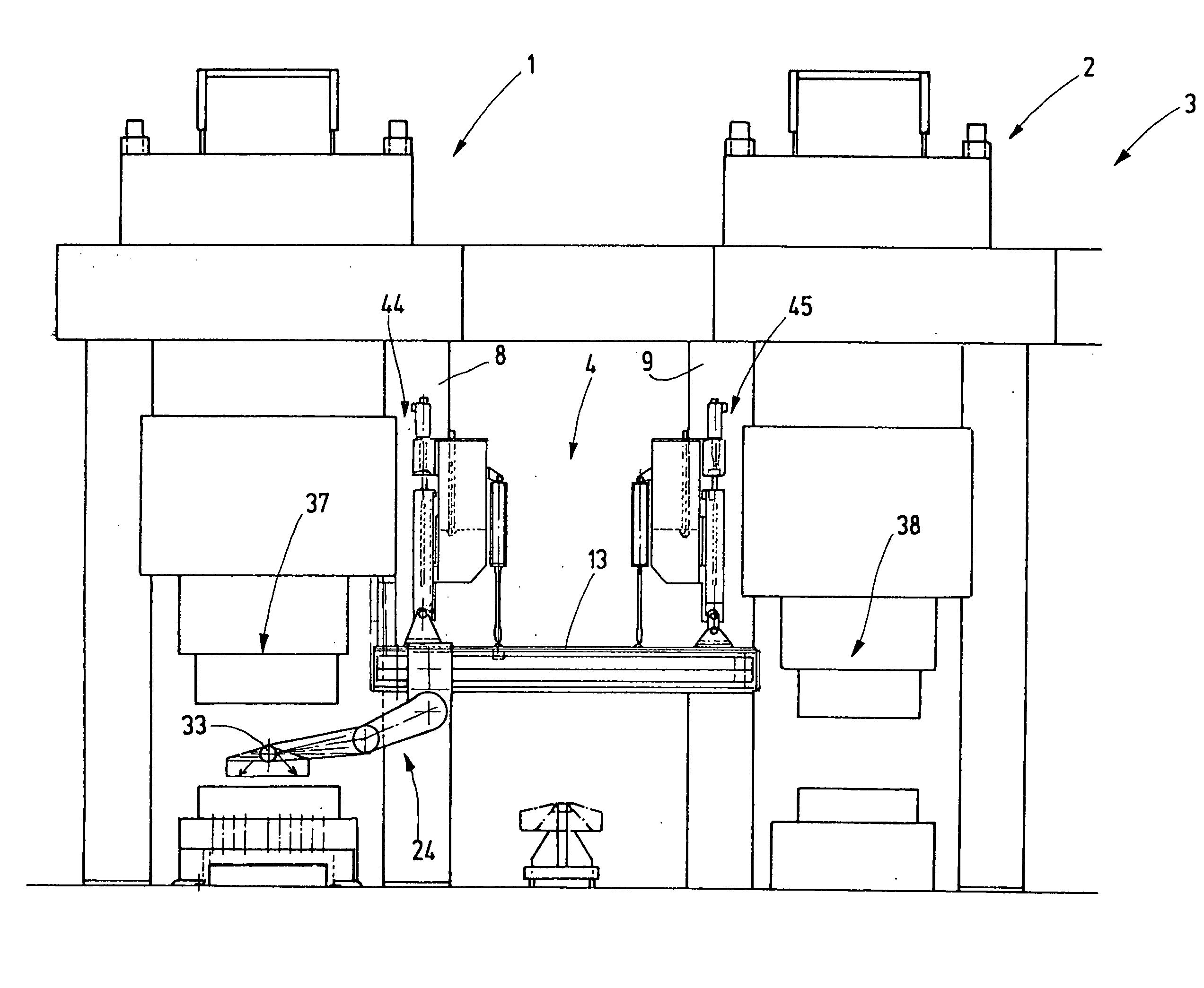
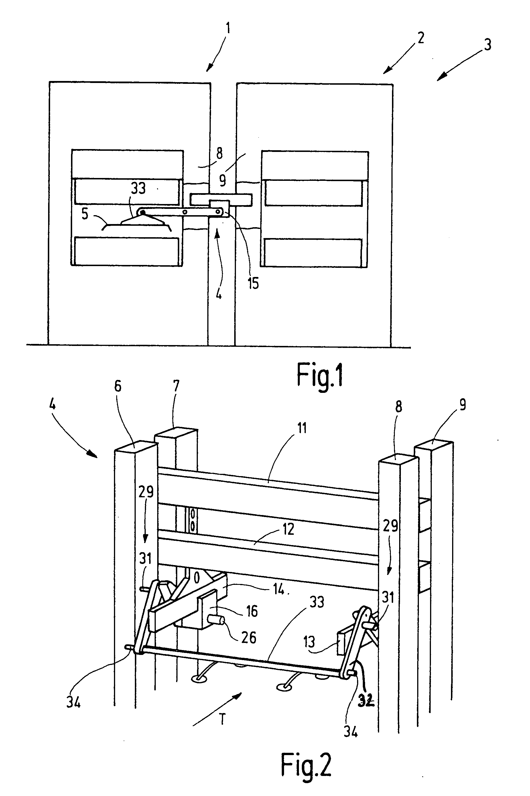
[0026]FIG. 1 shows an arrangement of two presses 1, 2 of a setup of presses 3 which are interconnected by a workpiece transfer system. The workpiece transfer system comprises individual transfer arrangements of which one transfer arrangement 4 is schematically shown in FIG. 1. It is used for transferring metal sheet workpieces 5 from the press 1 to the press 2. The transfer arrangement 4 can be used, as shown, for the interconnection of individual presses or for the transport of workpieces n hybrid press installations or in transfer presses. The transfer arrangement 4 is shown separately in FIG. 2. It is arranged between adjacent columns 6, 7, 8, 9 of the adjacent presses 1, 2. Spaced parallel guide rails 13, 14 are supported on, or between, the columns 6, 7, and 8, 9 and beams 11, 12 extend transverse to the transport direction T. Guide carriages 15, 16 (FIGS. 1 and 2) are supported on the guide rails 13, 14 so as to be movable in the transport direction T. Although it would be pos...


PUM


Abstract

In a transfer arrangement and method for transferring a workpiece between first and second spaced locations along a guide rail with a carriage movably supported on the guide rail, a transfer arm is pivotally supported on the carriage and carries at its free end a workpiece holder which is accelerated by the carriage with the arm essentially stretched out in the movement direction out of, and decelerated into, the end positions, and, in an intermediate position, the carriage movement is slowed down or even reversed while the workpiece holder is moved along by a pivot movement of the arm.

Description

BACKGROUND OF THE INVENTION [0001] The invention relates to a transfer arrangement, particularly for a transfer press and to a method for transporting workpieces by means of a transfer arrangement including a guide track on which a carriage is movably supported. [0002] The transport of workpieces between individual presses has been mechanized for some time in connection with different press installations, workpiece conveyor lines from press-to-press and similar devices. Particularly for presses arranged closely adjacent one another and for the handling of smaller sheet metal parts, so-called gripper track transfer equipment has been used as shown for example in DE 43 10 057 A1. With this kind of equipment, the workpieces are transferred by means of two parallel gripper rails which are moved in the rhythm of the presses so that one is moved toward and below the workpiece on other gripper rails and then raised to support the workpiece and then, with the workpiece supported thereon is ...

Claims


Application Information

Patent Timeline
IPC IPC(8): B21D43/05B21D43/10B21D43/11B30B15/00B30B15/30B65G47/91B66C1/00
CPCB21D43/05Y10S414/13B65G47/914
Inventor SCHMEINK, MARTINLAUKE, ANDREASJAGER, GERDHOFELE, HANSTHUDIUM, KARLTHUDIUM, CLAUDIA MARIADANGELMAYR, ANDREAS
Owner SCHULER PRESSEN GMBH & CO KG
Why Eureka
Try Eureka