
Method and system for efficient power control with multiple modes

a power control and multiple mode technology, applied in the field of integrated circuits, can solve the problems of low power efficiency and power saving capabilities of linear regulators, out of market for poor power efficiency and power saving capabilities, and insufficient conventional systems, so as to reduce the amount of energy wasted during the power switching process and reduce the switching time. , the effect of energy saving

Inactive Publication Date: 2009-08-20
ON BRIGHT ELECTRONICS SHANGHAI
View PDF13 Cites 70 Cited by
  • Summary
  • Abstract
  • Description
  • Claims
  • Application Information

AI Technical Summary

Benefits of technology

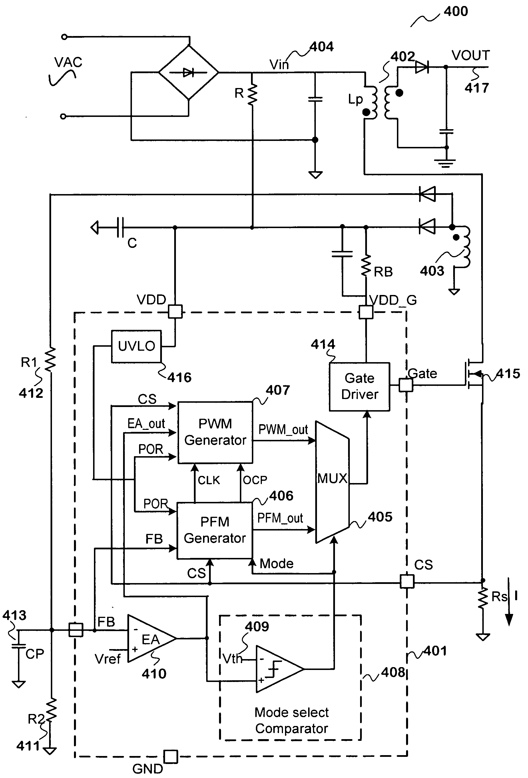
The present invention provides a power system that can selectively operate in different power modes based on operating conditions. The system includes a pulse-frequency modulation (PFM) component and a pulse-width modulation (PWM) component that work together to adjust the pulse width and frequency to regulate the output power. The system can selectively operate in a PWM mode or a PFM mode depending on the output power level and power consumption. The system can be used in both light and heavy loads, and it reduces energy waste and switching time compared to conventional techniques. The method and apparatus of the present invention provide an efficient and high-performance way to control power supply without substantial modifications to conventional equipment and processes.

Problems solved by technology

In comparison, linear regulators are becoming less popular and may be out of market for its poor power efficiency and power saving capabilities.
Unfortunately, these conventional system are often inadequate.

Method used


Image

  • Method and system for efficient power control with multiple modes
  • Method and system for efficient power control with multiple modes
  • Method and system for efficient power control with multiple modes

Examples


Embodiment Construction

[0032]The present invention is related to integrated circuits. More specifically, the present invention can be applied to devices used controlling power supply. According to various embodiments, the present invention provides various power control schemes to improve system stability and performance. Merely by way of example, the present invention can be used in a power system that is selectively operable in various power modes based on operating conditions, such as the output power level, power consumption, etc. It is to be appreciated that the present invention has a broad range of applications.

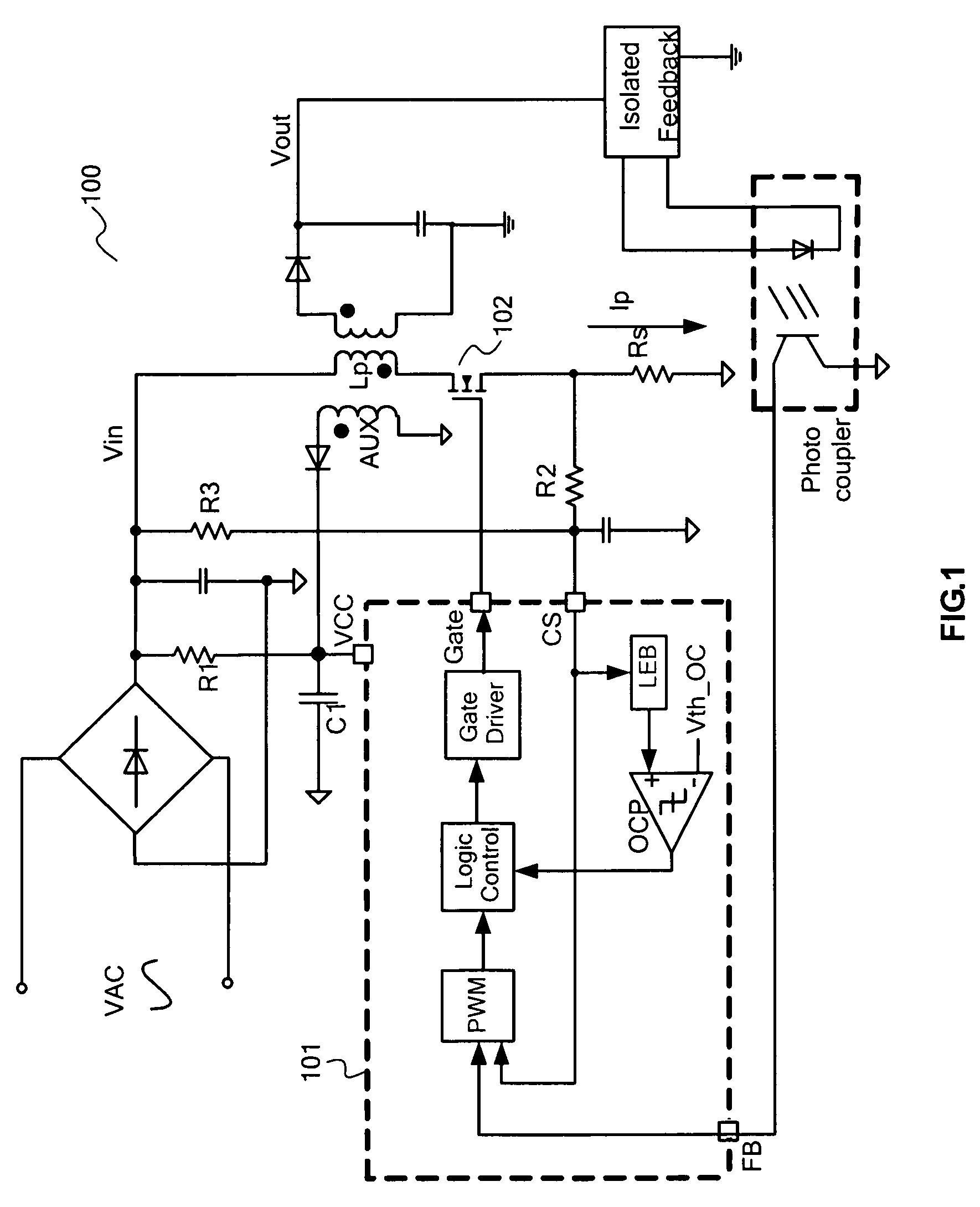
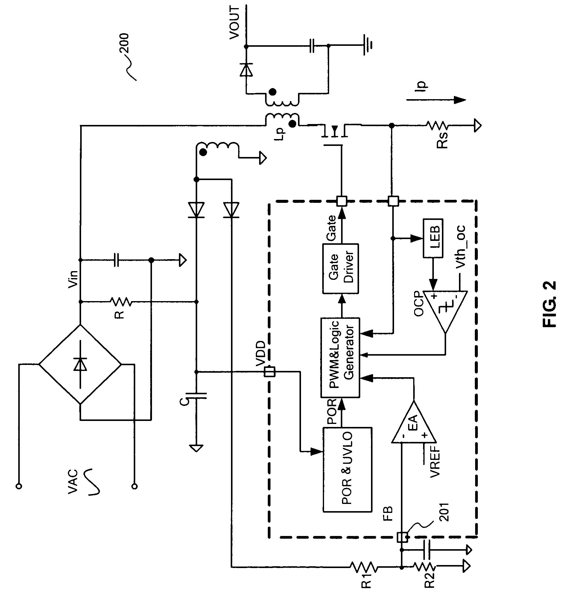
[0033]As described above, conventional system are often inadequate. For example, the system 100 as illustrated in FIG. 1 is often expensive to implement (e.g., due to added cost of switched power conversion system) and inefficient. In comparison, the system 200 as illustrated in FIG. 2 is relatively less expensive to implement, as various components used in the secondary side of system 100 i...


PUM


Abstract

Method and system for efficient power control with multiple modes. According to an embodiment, the present invention provides a power system with selectable power modes. The power system includes a first terminal for outputting energy, and the first terminal is electrically coupled to a load. The system also includes a pulse-frequency modulation (PFM) component that is configured to adjust a pulse frequency based on the load. The system additionally includes a pulse-width modulation (PWM) component that is configured to adjust a pulse width based on the load. The system further includes a switch that is electrically coupled to the first terminal. Also, the system includes a control component, the control component being configured to provide a control signal that is capable of causing the switch to be turned on or off. The control signal is associated with an output of the PWM component and the pulse width if an output is greater than a predetermined value. The control signal is associated with an output of the PFM component and the pulse frequency if an output is lower than a predetermined value.

Description

CROSS-REFERENCES TO RELATED APPLICATIONS[0001]This application claims priority to Chinese Patent Application No. 200810033749.0, filed Feb. 18, 2008, entitled “Method and System for Efficient Power Control with Multiple Modes,” by inventors Xiuhong Zhang, Zhen Zhu, Yaming Cao, and Lieyi Fang, commonly assigned, incorporated by reference herein for all purposes.STATEMENT AS TO RIGHTS TO INVENTIONS MADE UNDER FEDERALLY SPONSORED RESEARCH OR DEVELOPMENT[0002]NOT APPLICABLEREFERENCE TO A “SEQUENCE LISTING,” A TABLE, OR A COMPUTER PROGRAM LISTING APPENDIX SUBMITTED ON A COMPACT DISK[0003]NOT APPLICABLEBACKGROUND OF THE INVENTION[0004]The present invention is related to integrated circuits. More specifically, the present invention can be applied to devices used controlling power supply. According to various embodiments, the present invention provides various power control schemes to improve system stability and performance. Merely by way of example, the present invention can be used in a ...

Claims


Application Information

Patent Timeline
Patent Type & Authority Applications(United States)
IPC IPC(8): G05F1/00
CPCH02M3/33507Y02B70/16H02M2001/0032Y02B70/10H02M1/0032
Inventor ZHANG, XIUHONGZHU, ZHENCAO, YAMINGFANG, LIEYI
Owner ON BRIGHT ELECTRONICS SHANGHAI
Learn More