Stent with flexible elements

Active Publication Date: 2005-10-27
GYRUS ACMI INC (D B A OLYMPUS SURGICAL TECH AMERICA)
View PDF41 Cites 32 Cited by
  • Summary
  • Abstract
  • Description
  • Claims
  • Application Information

AI Technical Summary

Benefits of technology

[0015] An embodiment of the present invention relates to a stent comprising a tubular member having a body portion, a proximate end portion, and a distal end portion, the tubular member having an axial lumen therein adapted to provide fluid communication from the distal end portion to the proximal end portion, the tubular member further comprising a resilient distal transition region coupling the distal end portion to the body portion. One advantage of this embodiment of the invention is, for example, that the resilient distal transition region increases patient comfort by providing enhanced flexibility to accommodate the bending and stretching of the anatomy. A second advantage of this embodiment of the invention is, for example, that the resilient distal transition region improves stent retention within the anatomy.
[0016] In a

Problems solved by technology

Blockage of ducts in the body can be a serious and very painful affliction that can result in death if not promptly and effectively treated.
Alternatively, cysts or tumors growing against the outer wall of the ducts can cause constriction of the ducts.
The problem with making the shaft extremely soft is its lack of stiffness makes it difficult to insert it into the patient.
Stiff stents are believed to be felt by the muscle spasm of the ureter, potentially causing patient discomfort.
Further, the axial stiffness of current stents may not be ideal for comfort to the urinary tract anatomy without being felt by the patent.
Ureteral stents with smaller diameters are usually easier to insert but may provide insufficient drainage, whereas stents with larger diameters allow for increasing drainage capacity through the ureter but may be difficult to insert.
Stiff ureteral stents are also easier to insert than are softer stents, but once inserted can lead to increased patient discomfort.
Stiff stents are less likely to accommo

Method used


Image

  • Stent with flexible elements
  • Stent with flexible elements
  • Stent with flexible elements

Examples


Embodiment Construction

[0018] Reference will now be made to embodiments illustrated in the drawings and specific language which will be used to describe the same. It will nevertheless be understood that no limitation of the scope of the invention is thereby intended, such alterations and further modifications in the illustrated devices, as such further applications of the principles of the invention as illustrated therein as being contemplated as would normally occur to one skilled in the art to which the invention relates.

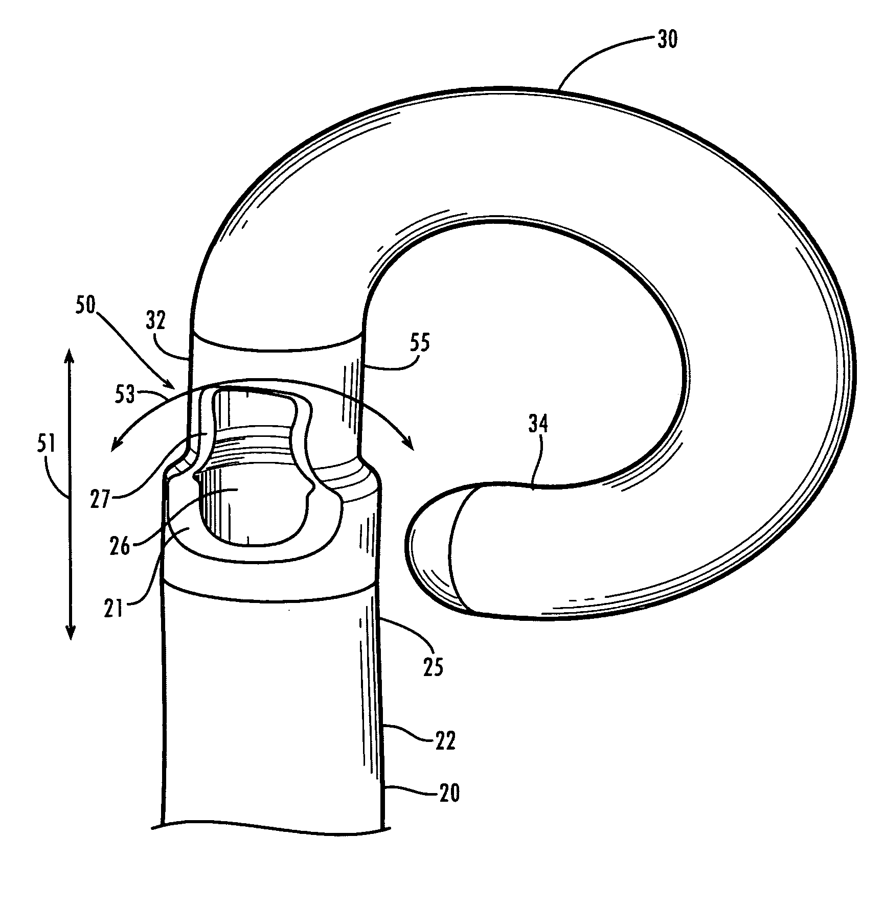
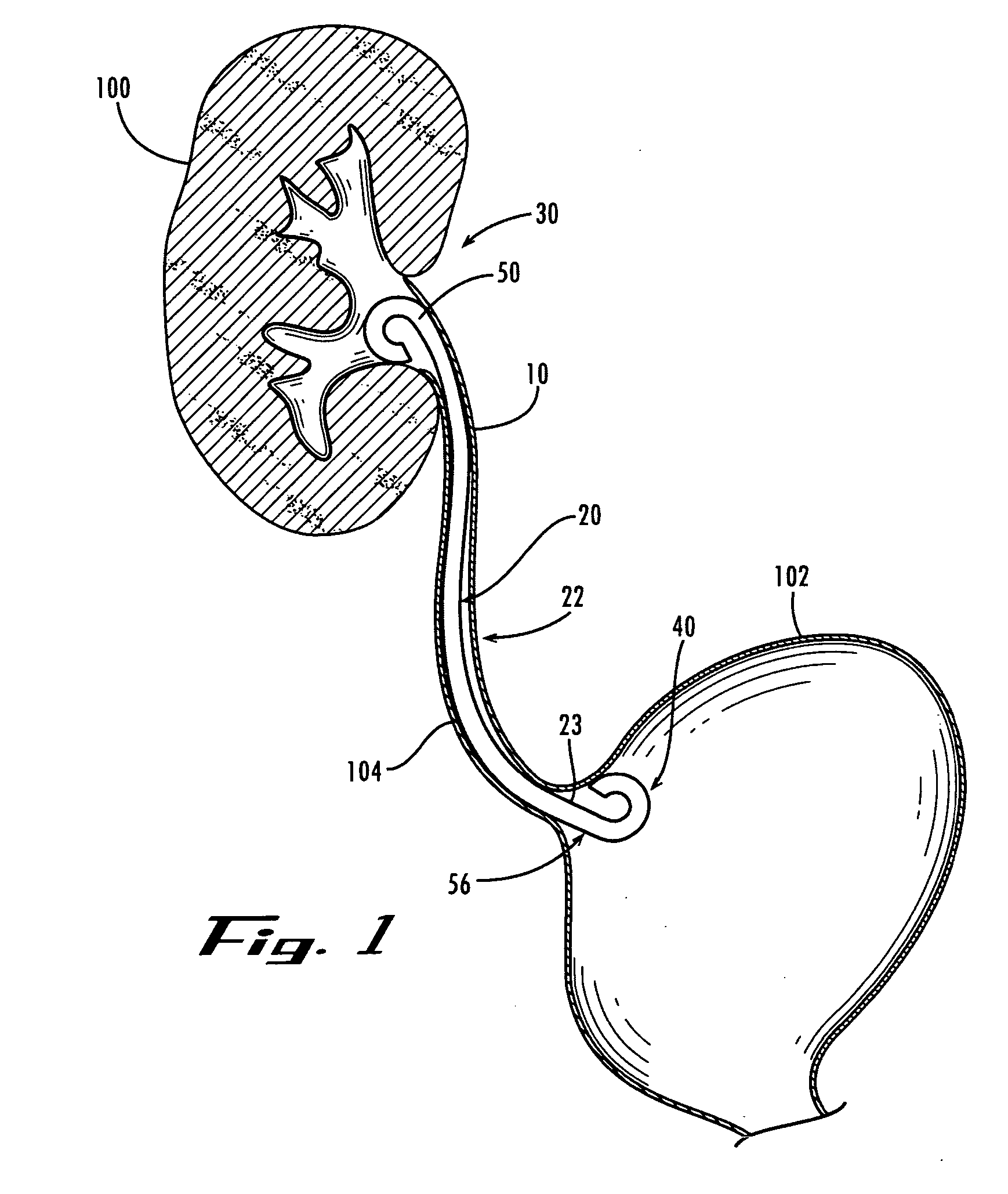
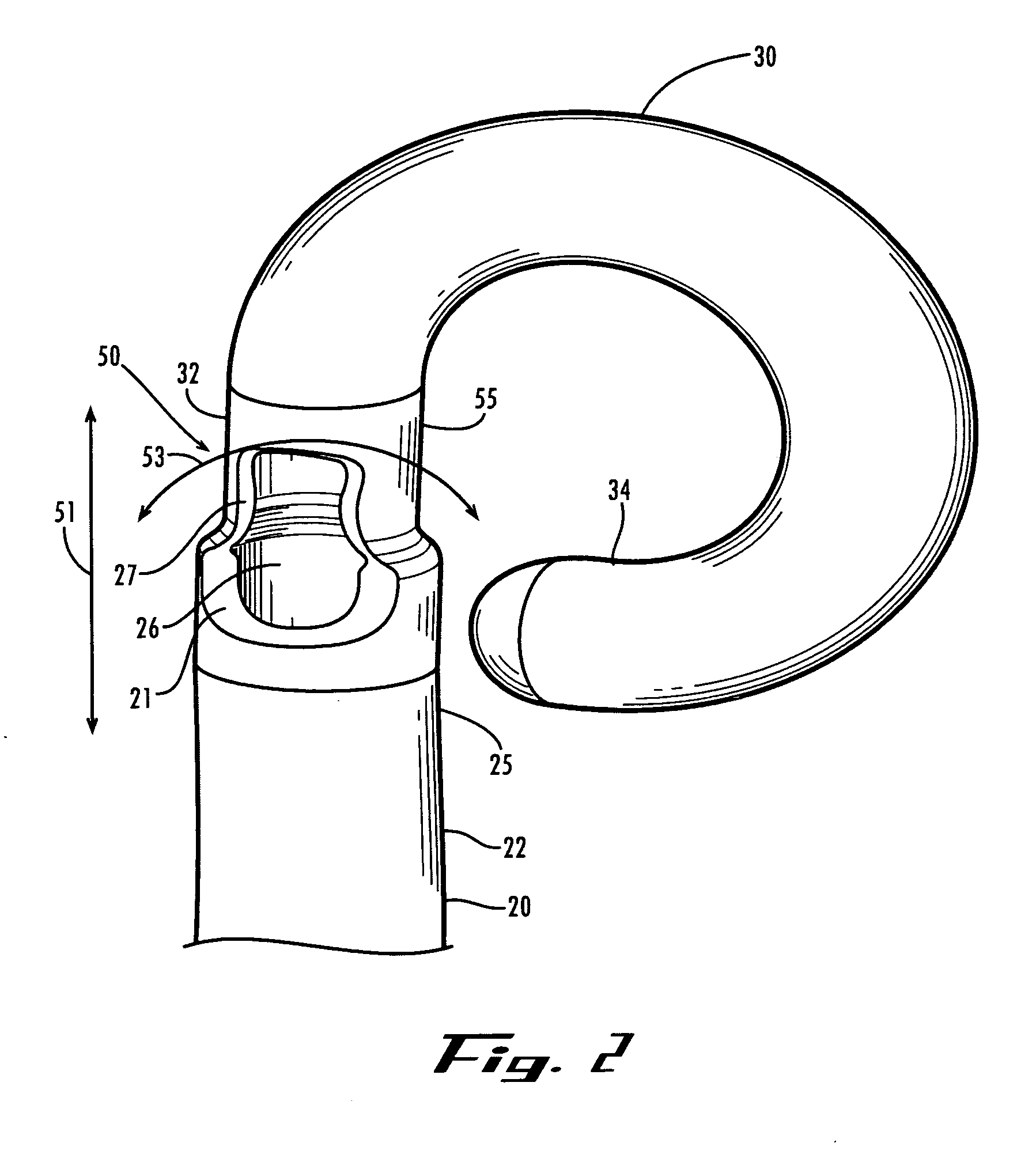
[0019] The invention relates to embodiments of medical devices (e.g., stents) for draining fluids. The invention increases patient comfort and prevents fluid retention if a stricture in a vessel develops. For simplicity and illustration, embodiments of the invention are described herein in the context of draining urine from a kidney, through a ureter, and into the bladder. However, the invention is applicable to any situation that requires drainage within a body, from a body, or from o...


PUM


Abstract

In accordance with the invention, there are provided medical devices for providing a fluid passage between two areas in the body. An embodiment of the present invention relates to a stent comprising a tubular member comprising a distal transition region and a proximal transition region adapted to provide the ability for the stent to accommodate the dynamic urinary tract anatomy that stretches and relaxes. The distal transition region and the proximal transition region is adapted to exhibit a physical property that provides both longitudinal elasticity, allowing for stretch and recoil, as well as radial elasticity, allowing for bending and recovery.

Description

FIELD OF THE INVENTION [0001] The present invention is related to ureteral stents, and more particularly, to methods and apparatus for stent shaft improvement. BACKGROUND [0002] Tubular prostheses, commonly called stents, are used in a variety of medical procedures. For example, stents are often used in connection with assisting drainage from the kidney through the ureter, from the liver through the biliary ducts, from the dorsal or ventral pancreas through the pancreatic ducts, from the gall bladder through the cystic, hepatic, or common bile ducts, and the like. A leading reason for stent deployment in ducts is to provide drainage to circumvent a blockage. Blockage of ducts in the body can be a serious and very painful affliction that can result in death if not promptly and effectively treated. Blockages can occur for a number of reasons. For example, stones or debris from such stones can pass from into the ureter, where they become entrapped. Similarly, stones or debris can pass ...

Claims


Application Information

Patent Timeline
IPC IPC(8): A61F2/04A61M29/02
CPCA61M27/008A61F2/04
Inventor ALISKI, PETERNISHTALA, VASUSHIA, BENEDICTTREMAGLIO, ANTHONY
Owner GYRUS ACMI INC (D B A OLYMPUS SURGICAL TECH AMERICA)
Why Eureka
Try Eureka