Dental prosthesis

a dental arch and prosthesis technology, applied in dentistry, dental prosthesis, medical science, etc., can solve the problems of unfavorable dental arch implants, unfavorable dental arch elaboration, and notably detrimental to dentists and dental technicians, and achieve the effect of simple dental arch implants, easy replacement, and increased patient comfor

Inactive Publication Date: 2011-07-21
JUSTO MANUEL RUBIO CEBRIA
View PDF14 Cites 1 Cited by
  • Summary
  • Abstract
  • Description
  • Claims
  • Application Information

AI Technical Summary

Benefits of technology

[0032]Additionally, the primary insertion means and the secondary insertion means respectively comprise primary retention means and secondary retention means configured to fix the secondary structure on the primary structure after the vestibular insertion. Having a primary structure fixed on the implants, regardless of the secondary structure, enables to adopt working modes which greatly simplify the dentist's o dental technician's work and they increase patients comfort. For example, in case of having to fix any definitive prosthesis, said prosthesis can be easily replaced by a provisional prosthesis, since it is only necessary to release the secondary structure from the primary structure, which is permanently attached to the implants. The primary retention means and the secondary retention means are also designed to facilitate these tasks. In this sense, we contemplate different solutions that can be used independently or jointly.
[0033]In the first solution, the primary retention means and the secondary retention means comprise a plurality of lateral orifices respectively located on the lateral wall and on the lateral covering wall, suitable for the use of retention pins. Even though screws can also be used, retention pins have the advantage of faster mounting and dismounting.

Problems solved by technology

There are numerous situations in which implants of the dental arch are in unfavourable conditions, such as due to excess inclination, for being out of the natural space of the tooth or for not being subgingival (deep under the gum), among others.
All these situations are not only highly problematic for the patient, who suffer all the discomfort without getting the desired aesthetic results, but they are also notably detrimental to dentists and dental technicians.
However, the elaboration of this type of prostheses is quite complex, presents multiple adjustment difficulties and even aesthetic problems.
For example, any small variation in the final position of the chimney in the prosthesis with respect to its original position in the mouth can cause serious adjustment problems.
It is also frequent that the holes drilled by chimneys are in highly visible areas of the dental piece, due to a faulty placement of implants, which results in undesired aesthetic results.
Another very important aspect is the possibility of chimneys being located in highly occluded areas (cuspids o pits), which produces failures in the prosthesis function.
As regards cemented prostheses, these are also mounted and dismounted by axial insertions, yet they do not have as many elaboration and mounting inconveniences as screwed prostheses since they do not use chimneys.
In spite of the apparent simplicity of this type of prosthesis, its elaboration and mounting still produces some of the aforementioned problems.
Particularly, wrong implant placement can cause important inconveniences such as, for example difficulties placing the first pieces which can seriously hinder the fitting with second pieces placed in the prostheses.
It may also be the case that there exist small variations in the final position of the second pieces on the prosthesis in relation with their original position in the mouth, which causes serious adjustment problems.

Method used


Image

  • Dental prosthesis
  • Dental prosthesis
  • Dental prosthesis

Examples


Embodiment Construction

)

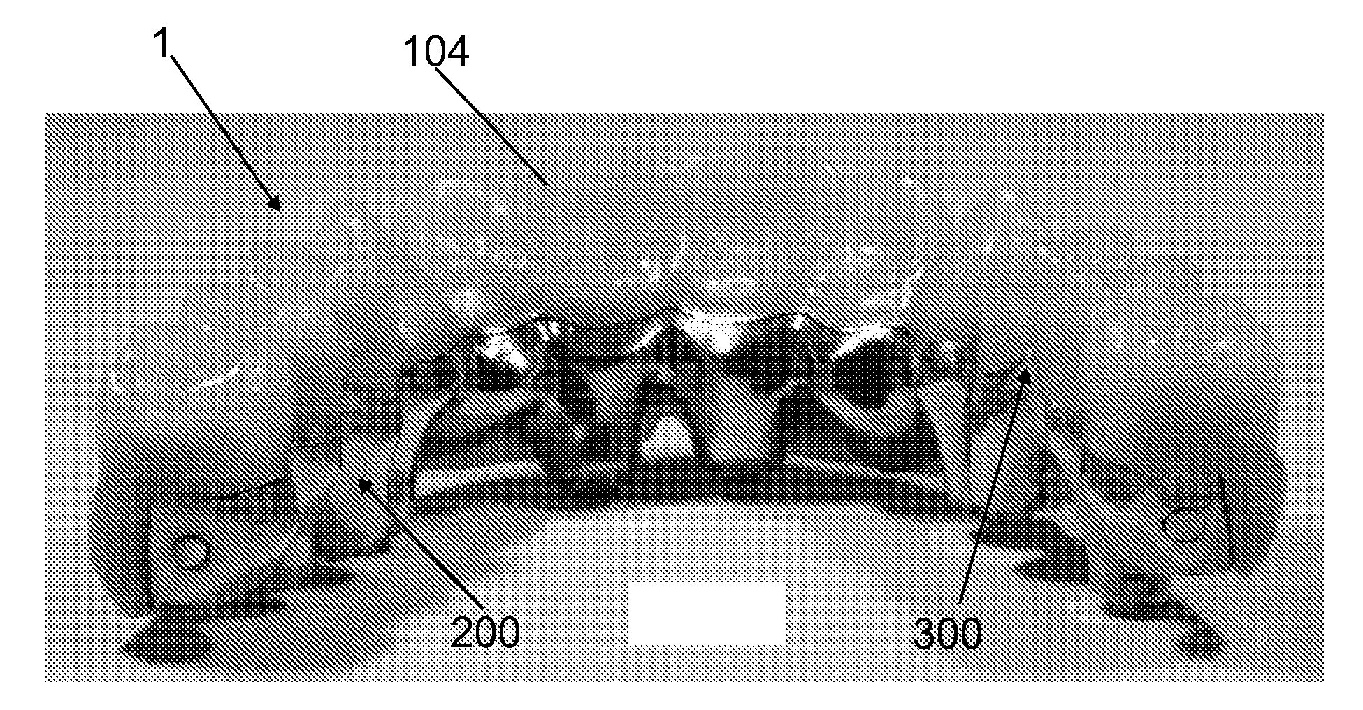
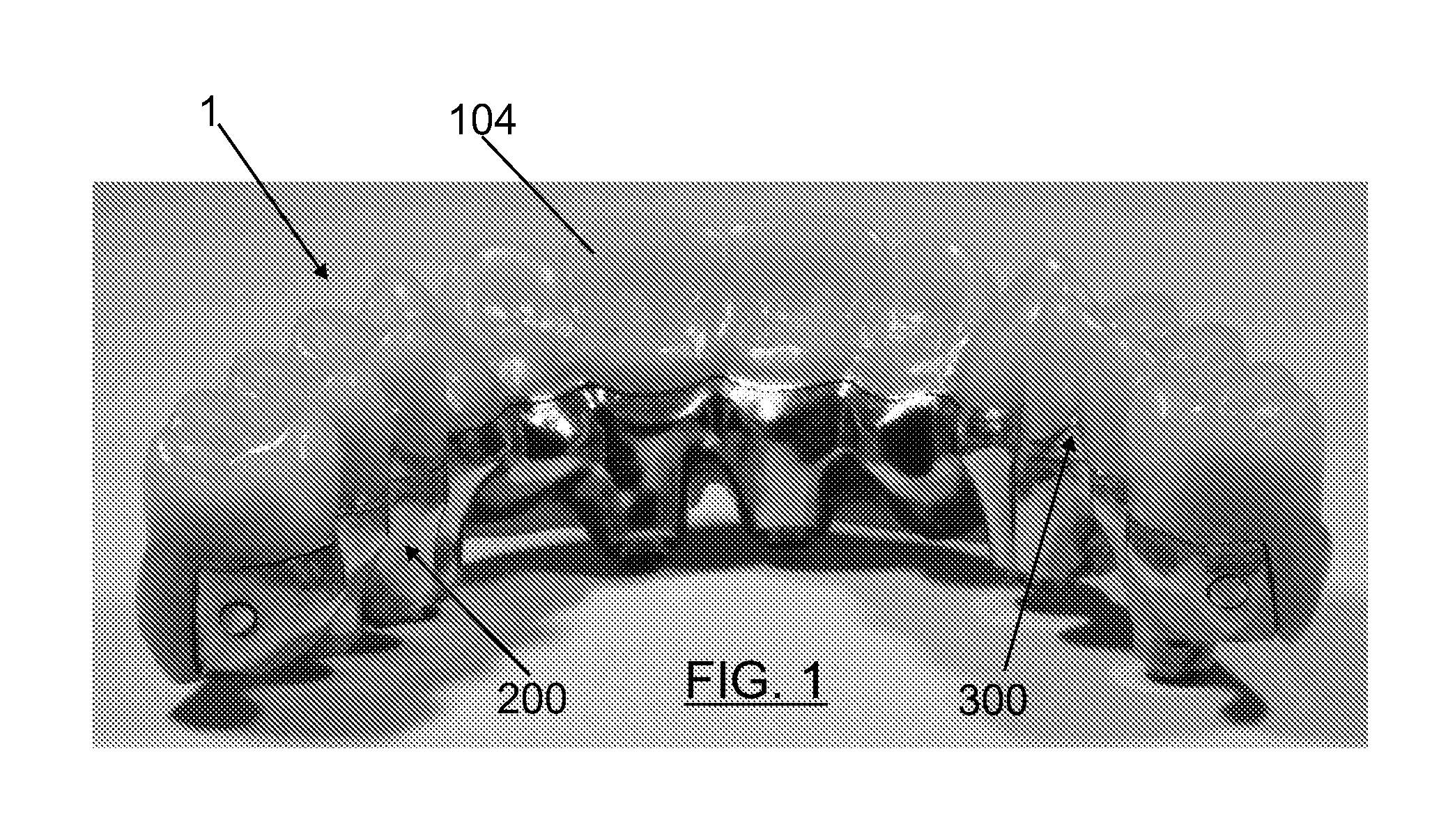
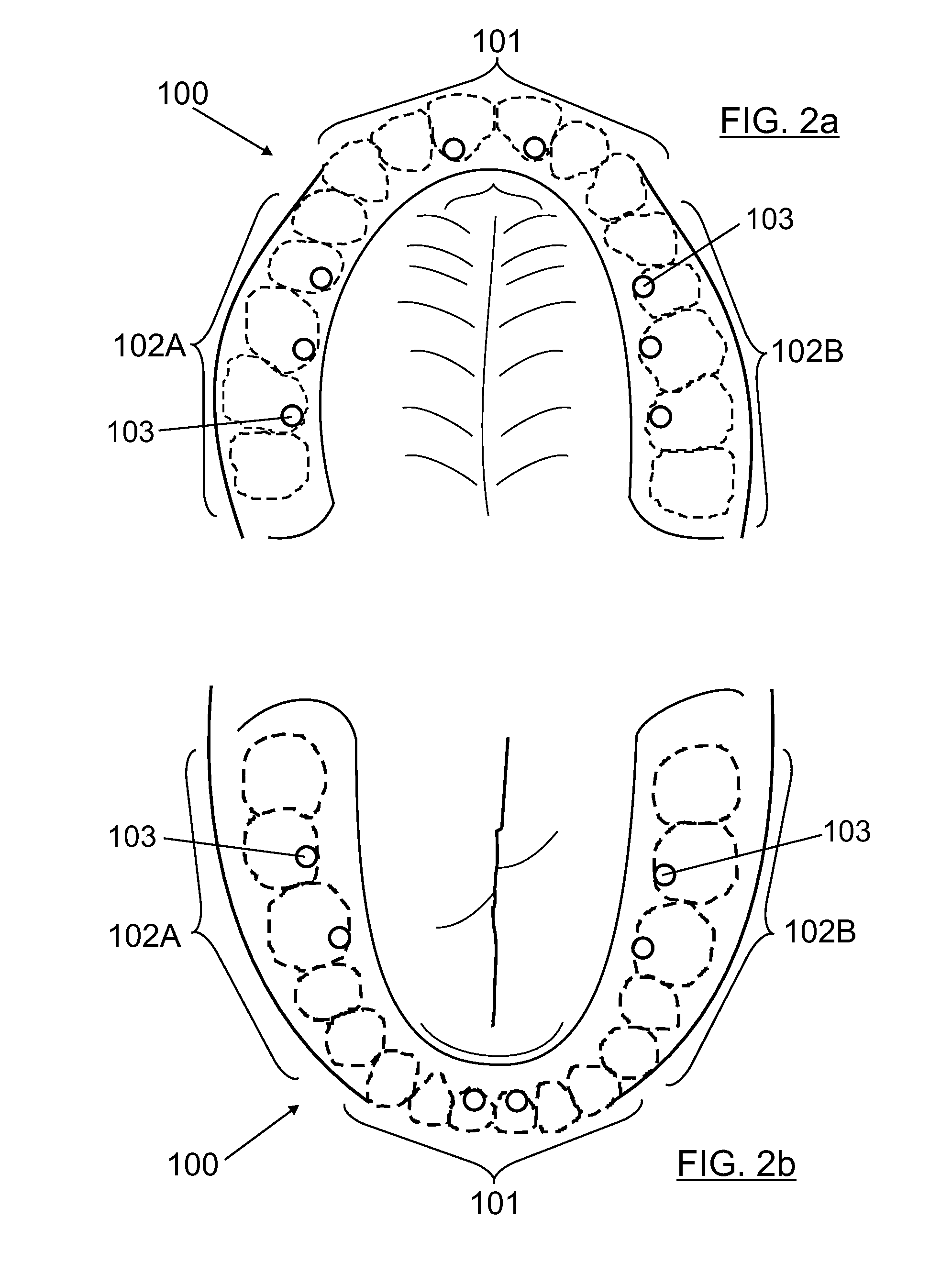
[0052]FIG. 1 shows a dental prosthesis (1) according to the present invention. As it can be seen, this prosthesis (1) is of the type that are fixed on a plurality of implants (103) arranged in a dental arch (100), as the ones shown in FIGS. 2a and 2b. Said prosthesis (1) comprises:[0053]a primary structure (200) which is configured to be screwed on the implants (103) of the dental arch (100) and which has primary insertion means (410, 420, 430, 440); and

[0054]a secondary structure (300) which is configured to support a reproduction (104) of the teeth and of the gum of the dental arch (100) and which has secondary insertion means (510, 520, 530, 540).

[0055]Also, the primary insertion means (410, 420, 430, 440) and the secondary insertion means (510, 520, 530, 540) are configured to work in collaboration and allow the coupling of the secondary structure (300) on the primary structure (200) through a vestibular insertion.

[0056]The prosthesis (1) of the present example is intended for ...


PUM


Abstract

Dental prosthesis to be fixed on implants (103) is arranged in a dental arch (100), completely or partially edentulous. The prosthesis (1) includes a primary structure (200) which is configured to be screwed on the implants (103) of the dental arch (100) and which has primary inserts (410, 420, 430, 440); and a secondary structure (300) which is configured to support a reproduction (104) of the teeth and of the gum of the dental arch (100) and which has secondary inserts (510, 520, 530, 540). The primary inserts (410, 420, 430, 440) and the secondary inserts (510, 520, 530, 540) are configured to work in collaboration and allow the coupling of the secondary structure (300) on the primary structure (200) through a vestibular insertion.

Description

[0001]This application claims benefit of Serial No. 201030033, filed 15 Jan. 2010 in Spain and which application is incorporated herein by reference. To the extent appropriate, a claim of priority is made to the above disclosed application.OBJECT OF THE INVENTION[0002]The present invention refers to a dental prosthesis of the type which are fixed on a plurality of implants arranged in a dental arch, completely or partially edentulous, corresponding to a patient's maxilla or mandible. Specially, for completely toothless patients or those who have a reduced number of teeth (natural or prosthetic).[0003]The dental prosthesis of the present invention has been specially designed to be easily mounted and dismounted in the patients mouth by a vestibular insertion, equivalent to a horizontal insertion. Similarly, the dental prosthesis of the present invention depends much less on the good or bad implant placement compared with existing prosthesis and it also presents an aesthetic finish.BAC...

Claims


Application Information

Patent Timeline
Patent Type & Authority Applications(United States)
IPC IPC(8): A61C13/103
CPCA61C8/0048
Inventor RUBIO CEBRIA, JUSTO MANUEL
Owner JUSTO MANUEL RUBIO CEBRIA
Why Eureka
Try Eureka