Removable closure system and plug for conduit

Inactive Publication Date: 2005-11-03
RED FLAME HOT TAP SERVICES
View PDF20 Cites 14 Cited by
  • Summary
  • Abstract
  • Description
  • Claims
  • Application Information

AI Technical Summary

Benefits of technology

[0013] Advantages of the present invention include simple installation and removal of the plug assembly into and from the tubular member, no mechanic

Problems solved by technology

However, the Lock-O-Ring™ system suffers from a number of disadvantages.
One primary disadvantage is that it requires the precise coaxial alignment of the plug's annular groove with the retainer ring in the flange, all while rotating the retainer screws to advance the ring.
A related problem is that if a worker rotates the screws before the plug is in place, it is possible for the retainer ring's segments to fall into the main pipeline.
Furthermore, the Lock-O-Ring™ system provides little, if anything, in the way of feedback to the operator to

Method used


Image

  • Removable closure system and plug for conduit
  • Removable closure system and plug for conduit
  • Removable closure system and plug for conduit

Examples


Example

[0022] Reference is to be had to the Figures in which identical reference numbers identify similar components.

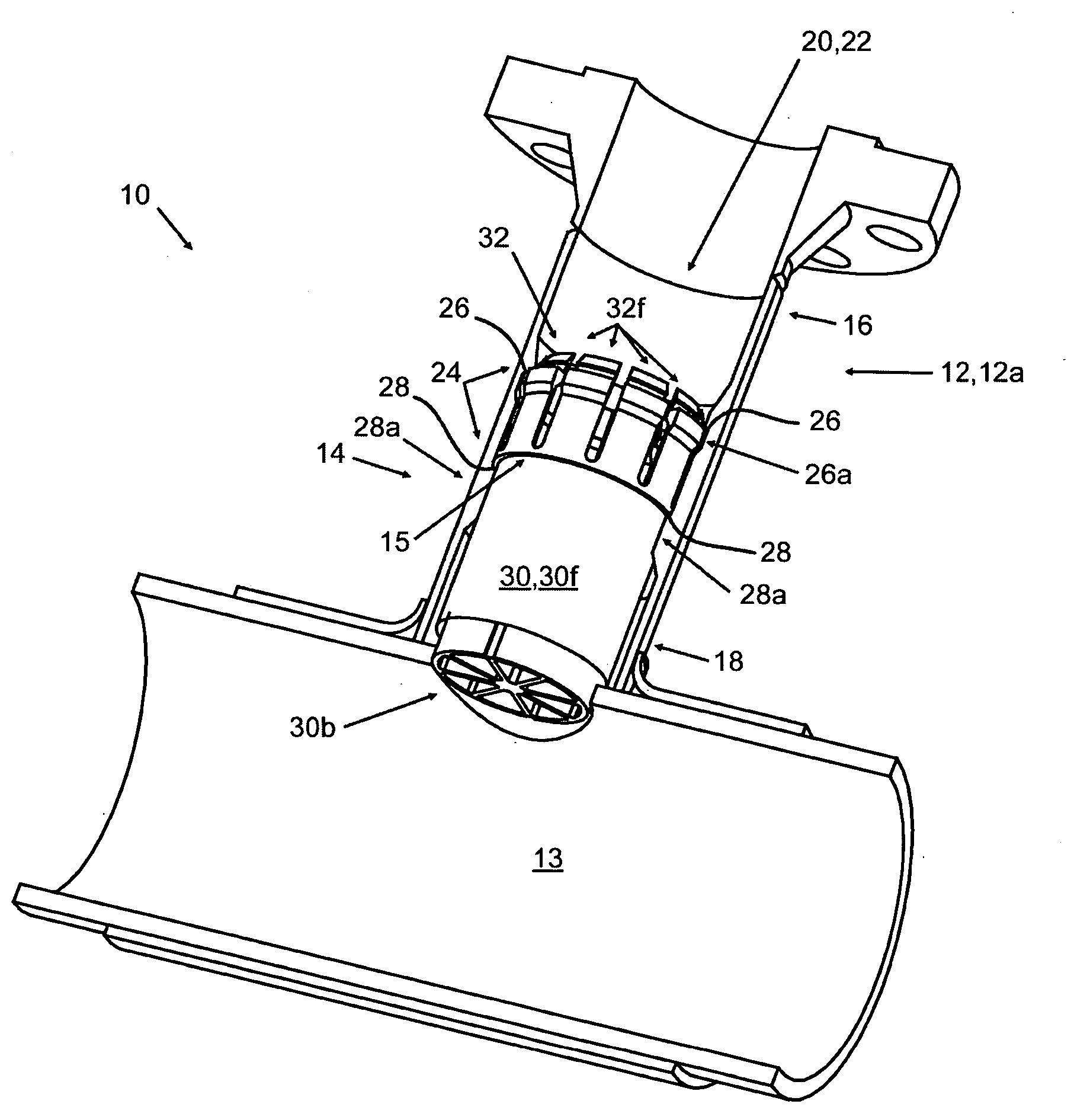
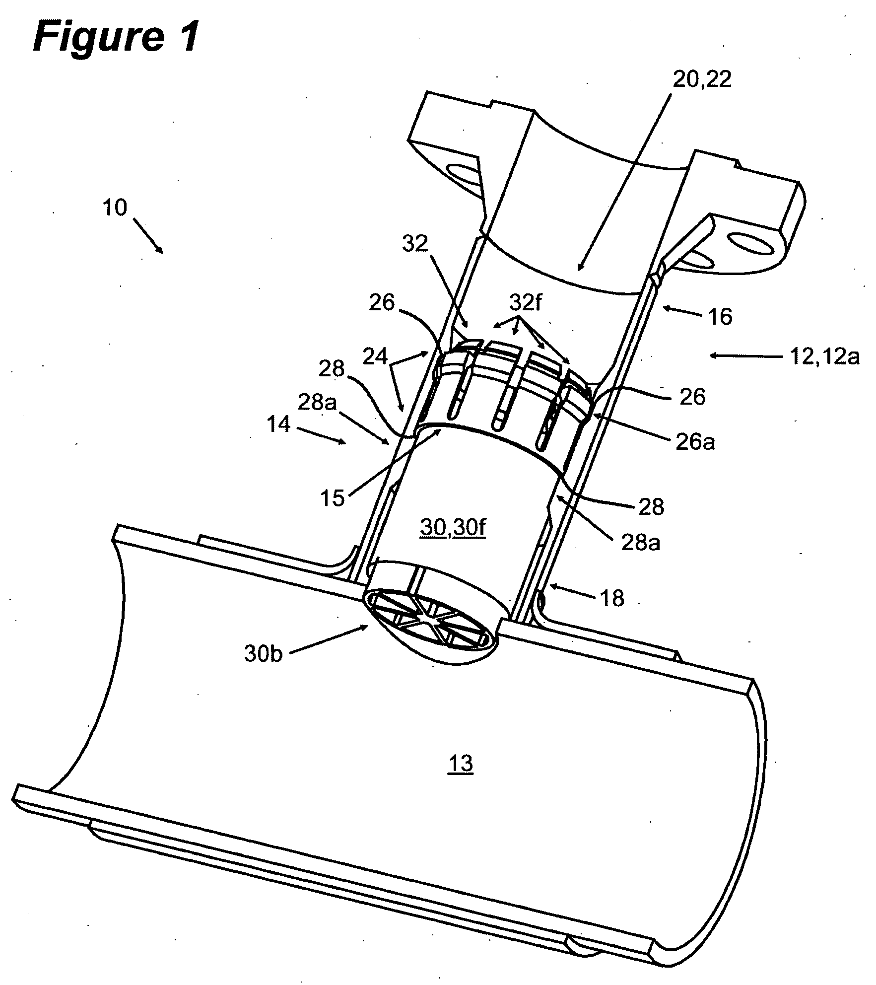
[0023] Referring to the Figures, the removable closure system 10 of the present invention comprises a tubular member 12 having a opening 20 for the passage of tools or for flow of liquids or gases therethrough and a plug assembly 14. The tubular member 12 may be a nipple 12a which is attachable to a pipeline 13. The invention herein is not limited in use only to a nipple 12a, but is a system for removably placing a plug assembly 14 inside any tubular member 12 or opening 20; the nipple 12a being example of a tubular member 12 and illustrated herein only because it is a typical environment for the application of the removable plug system 10 of this invention. For example, the tubular member 12 may also be a low-profile flange, a flanged section of pipe or a section of pipeline.

[0024] The tubular member 12 has an entrance end 16 and a plug end 18. The plug end 18 is shown of...


PUM


Abstract

The invention provides a removable closure system comprising a tubular member having an internal surface with an internal profile therein, an entrance end and a plug end, the internal profile providing a collet shoulder and a plug stopping shoulder. A plug assembly is positioned within the tubular member. The plug assembly has a plug suitable for insertion through the tubular member at the entrance end and past the collet shoulder, a collet with a plurality of collet fingers. The collet fingers are moveable between a collapsed and a normally expanded condition, the collapsed condition suitable for insertion of the plug assembly through the tubular member past the collet shoulder and the expanded condition suitable for engaging the collet shoulder. When the plug assembly is placed in the tubular member against the plug stopping shoulder, and the collet fingers are in the expanded condition engaging the collet shoulder, the plug assembly is removably secured in the tubular member.

Description

CROSS REFERENCE TO RELATED APPLICATION [0001] This application is a regular application of U.S. Provisional Patent Application Ser. No. 60 / 566,098 filed Apr. 29, 2004 and entitled, “NOVEL HOT TAPPING METHOD, SYSTEM AND APPARATUS”, the entirety of which is incorporated herein by reference.FIELD OF THE INVENTION [0002] The present invention relates generally to a system for removably placing a device inside a conduit, and more particular to a system for removably placing a plug, either solid or flow-through, in a branch pipeline or other tubular member which was hot tapped onto a main pipeline. BACKGROUND OF THE INVENTION [0003] In pipeline hot tapping operations it is frequently necessary to close, or to block access to, the interior of a tubular member either permanently or semi-permanently. Pipeline hot taps are used when repairing a defective area of a line without taking it out of service, by setting up a bypass line to provide a path for fluid flow while the defect is repaired. ...

Claims


Application Information

Patent Timeline
IPC IPC(8): F16L55/10F16L55/11
CPCF16L55/1141
Inventor SAYERS, JAREDDHALIWAL, AMANJEETEBL, DAVIDHAYES, DOUGLOYER, ALAIN
Owner RED FLAME HOT TAP SERVICES
Why Eureka
Try Eureka