
Limited electromagnetic radiation motor vehicle lighting device

Inactive Publication Date: 2016-12-22
VALEO VISION SA
View PDF1 Cites 2 Cited by
  • Summary
  • Abstract
  • Description
  • Claims
  • Application Information

AI Technical Summary

Benefits of technology

The patent aims to use cheap and simple methods to limit the electromagnetic fields emitted by cables in lighting devices. This will help to reduce interference and improve the overall performance of the lighting system.

Problems solved by technology

As a result, the magnetic fields diffused by the electric element outside the lighting device are limited.

Method used


Image

  • Limited electromagnetic radiation motor vehicle lighting device
  • Limited electromagnetic radiation motor vehicle lighting device
  • Limited electromagnetic radiation motor vehicle lighting device

Examples


first embodiment

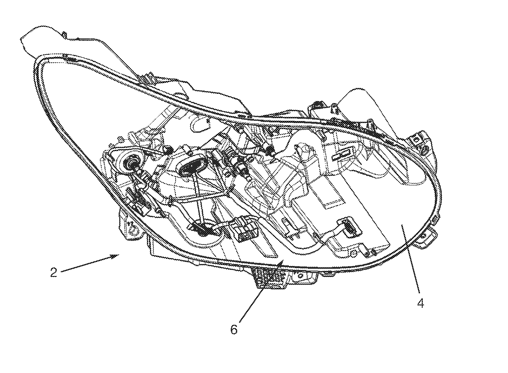
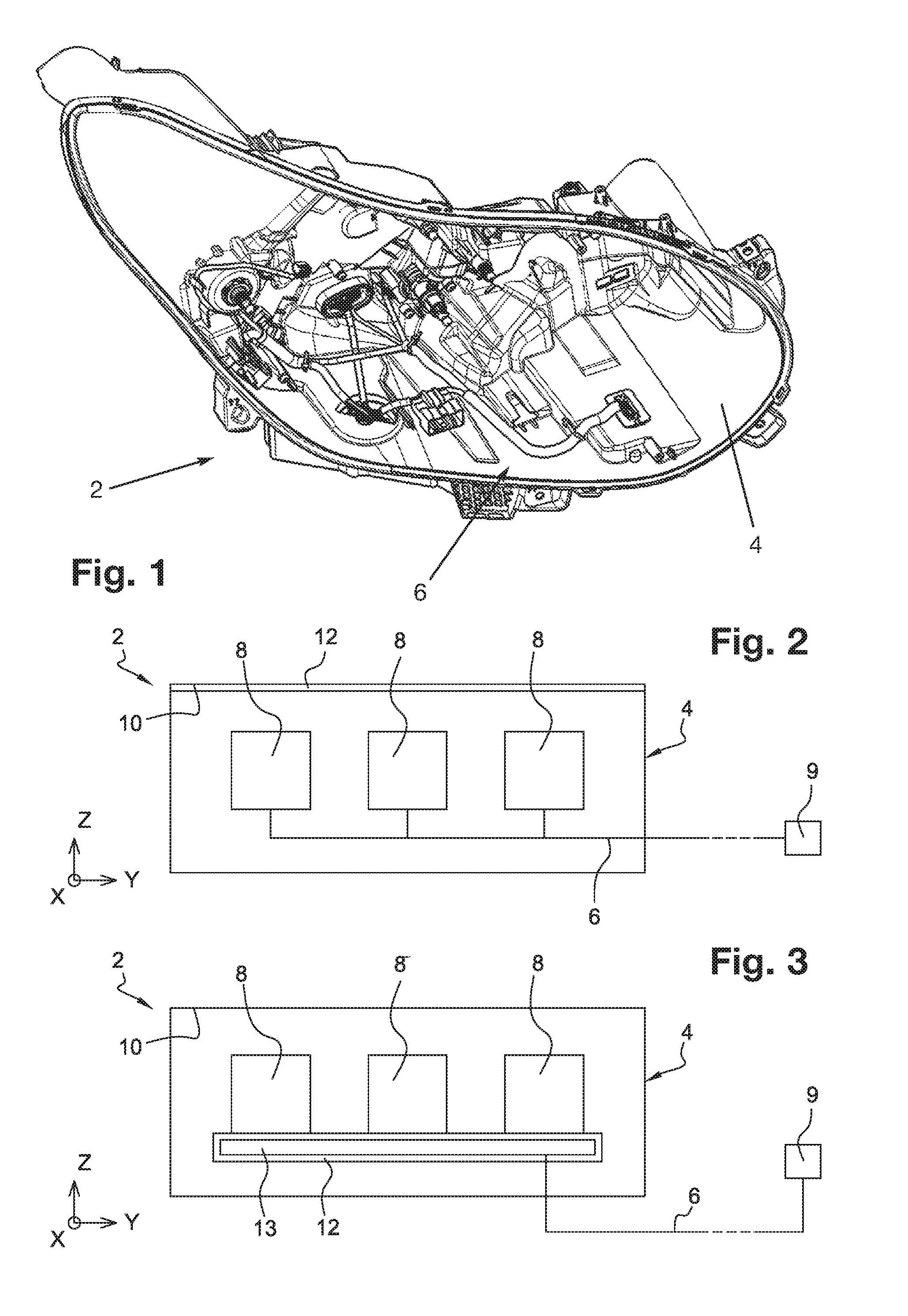
[0065]A motor vehicle lighting device 2 in accordance with the invention is shown in FIGS. 1 and 2. This lighting device 2 comprises an open casing 4 made from a polymer material.

[0066]At least one electric element 6 and optical means 8 adapted to form a light beam are retained in the casing 4 of the lighting device 2. The electric means or element 6 comprises at least one electric conductor. The optical means 8 notably comprise at least one light source, generally a plurality of light sources. The electric element 6 is intended to connect the light sources to electrical power supply and / or control means 9 generally situated in the vehicle outside of the lighting device 2. In the present case, the electric element 6 comprises a plurality of electric conductors. They could be any other electric element, however.

[0067]The lighting device 2 also comprises a protective outer lens (not shown) closing the casing 4. This protective outer lens is transparent to the visible light emitted by ...

second embodiment

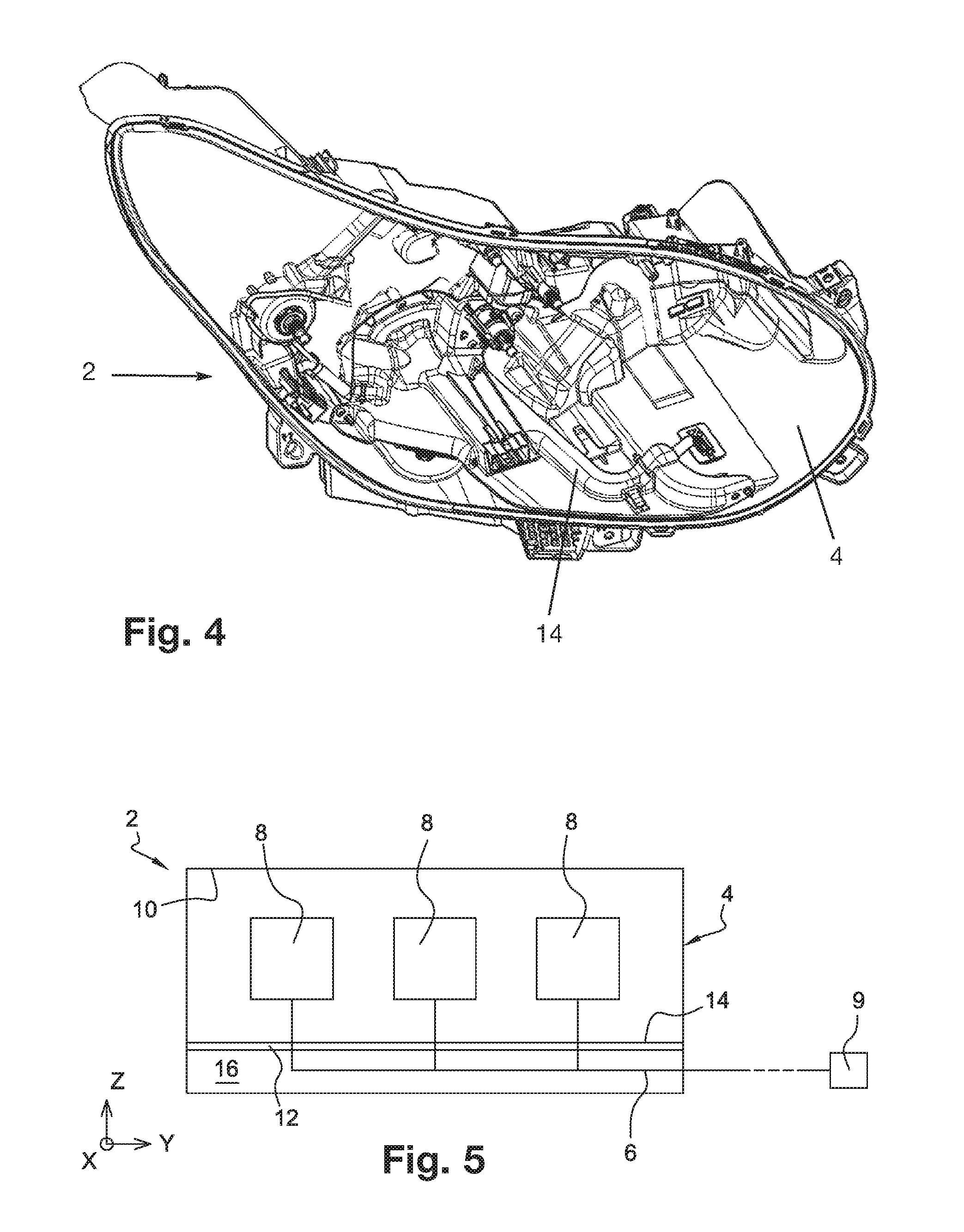
[0090]The second embodiment further differs from the first in that the first wall is formed by a wall of the guide element 14 and not by a portion of the internal surface 10 of the casing 4. As can be seen in FIG. 5, the electric conductors 6 are situated in the vicinity of the wall of the guide element 14 covered with the coating 12 by virtue of the guiding of the electric conductors 6. It is the side of the wall of the guide element 14 that is oriented toward the confinement housing 16 that is provided with the coating 12. The coating 12 is therefore effective at reflecting the electromagnetic rays emitted by the electric conductors 6.

[0091]By way of a variant of this second embodiment, the lighting device 2 may further comprise a second wall at least partially covered with the coating 12, the first wall being part of the guide element 14 and the second wall being part of a portion of the casing 4 of the lighting device 2. These first and second walls delimit the confinement housi...


PUM


Abstract

A motor vehicle lighting device, comprising at least one electric element and at least one first wall delimiting an area on which or in which the electric element is retained, this first wall being at least partly covered with an electrically conductive coating forming electromagnetic shielding.

Description

CROSS-REFERENCE TO RELATED APPLICATIONS[0001]This application claims priority to the French application 1555682 filed Jun. 22, 2015, which applications are incorporated herein by reference and made a part hereof.BACKGROUND OF THE INVENTION[0002]1. Field of the Invention[0003]The present invention concerns the technical field of motor vehicle lighting devices. The invention more particularly concerns an electromagnetically shielded motor vehicle lighting device provided with.[0004]2. Description of the Related Art[0005]A motor vehicle generally includes lighting devices forming various lighting or signaling lights. A lighting device notably includes a light source emitting a light beam and various optical elements. In order to connect this light source to electrical power supply means and / or to control means, the lighting device generally includes for this purpose a plurality of electric conductors, notably electric cables.[0006]However, the current flowing in the electric cables gen...

Claims


Application Information

Patent Timeline
IPC IPC(8): F21S8/10
CPCF21S48/30F21S45/00F21S45/10
Inventor FAOUCHER, ERWANHERMITTE, MICHELGRATECAP, FRANCOISJUTON, MICHEL
Owner VALEO VISION SA
Learn More