
Method of operating a wormgear drive at high energy efficiency

a technology of worm gear drive and high energy efficiency, which is applied in the direction of gears, mechanical equipment, fuels, etc., can solve the problems of loss of power transmission efficiency, increase in oil temperature of oil reservoirs, bulk oil, and failure to teach the effect of friction reduction, and achieve low traction coefficient and high energy efficiency

Inactive Publication Date: 2005-11-03
CHEVROU USA INC
View PDF11 Cites 162 Cited by
  • Summary
  • Abstract
  • Description
  • Claims
  • Application Information

AI Technical Summary

Benefits of technology

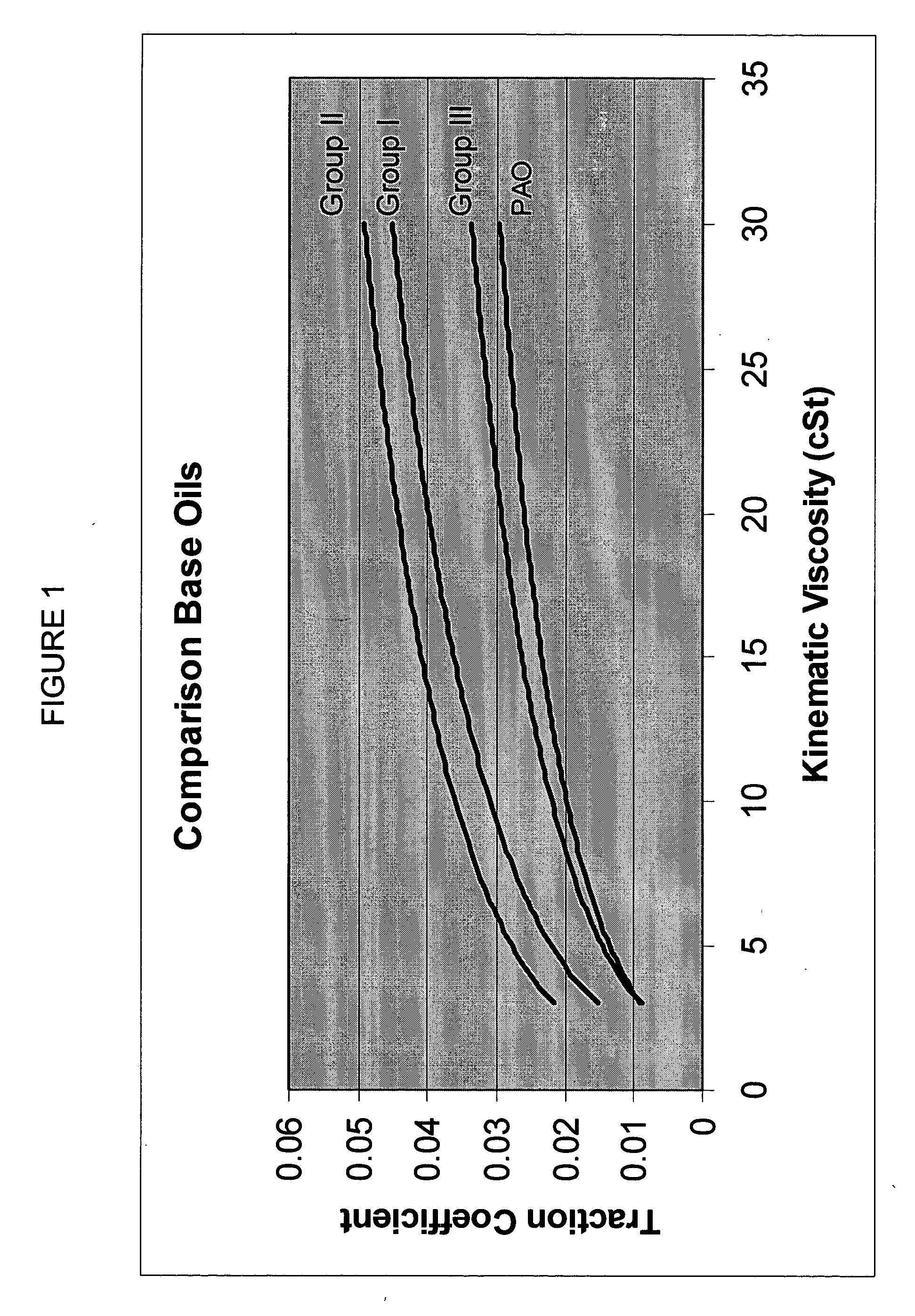
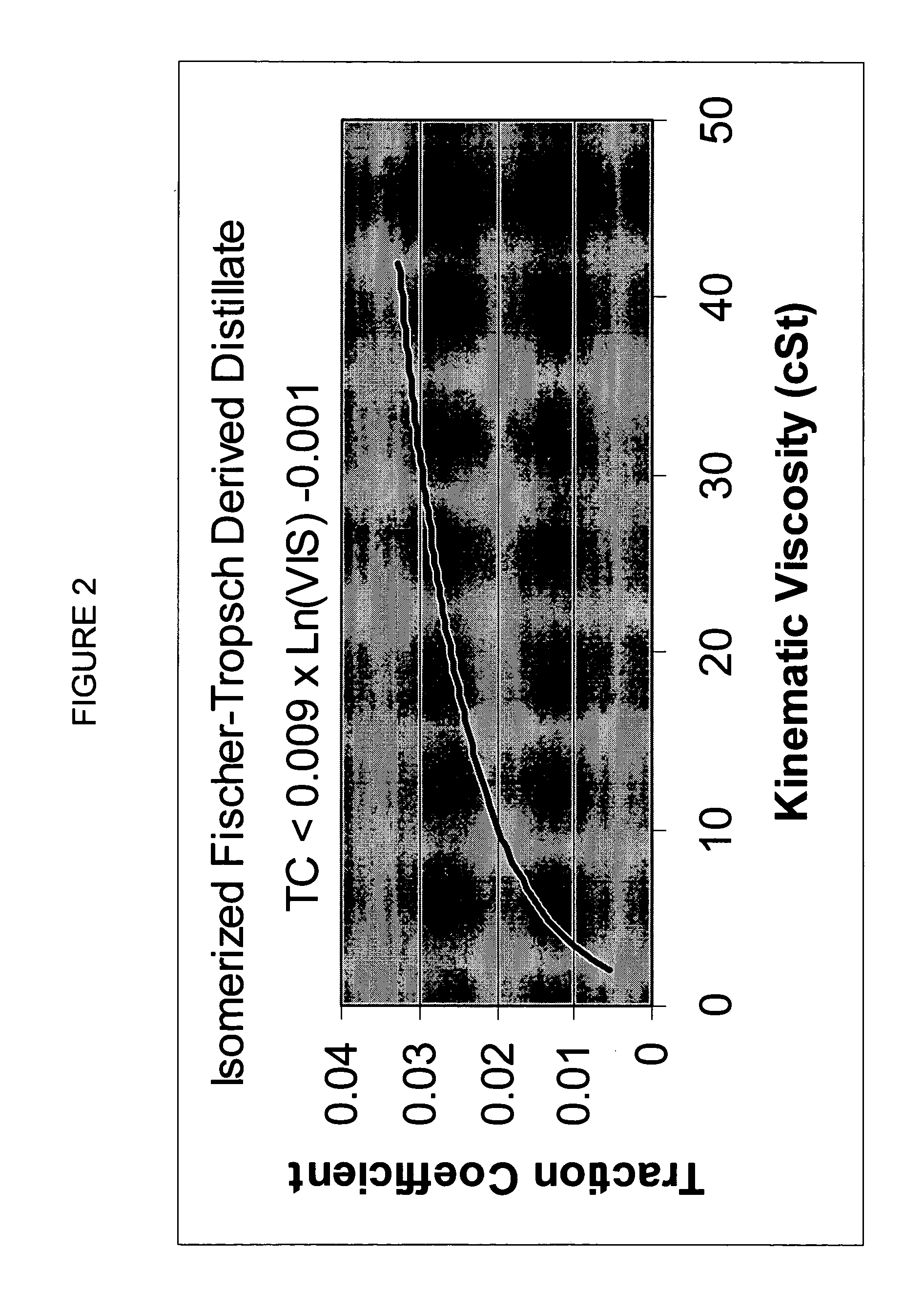
[0016] The present invention is also directed to a process for reducing the traction coefficient of a higher-traction coefficient lubricating base oil, by recovering a lower-traction coefficient isomerized Fischer-Tropsch derived distillate fraction having a traction coefficient less than 0.023 when measured at a kinematic viscosity of 15 cSt and a slide to roll ratio of 40 percent, and blending the lower-traction coefficient isomerized Fischer-Tropsch derived distillate fraction with the higher-traction coefficient lubricating base oil in the proper proportion to produce a lubricating base oil blend having a traction coefficient less than the traction coefficient of the higher-traction coefficient lubricating base oil when measured at a kinematic viscosity of 15 cSt.

Problems solved by technology

Unlike ordinary gears, the motion is not reversible, a worm can drive a gear to reduce speed but, in general, a gear cannot drive a worm to increase it.
The frictional heat that is generated by this movement manifests itself as a loss of power transmission efficiency [horsepower loss] and leads to a rise in temperature of oil in the oil reservoir, or bulk oil.
This application does not teach that there is any benefit for friction reduction.

Method used


Image

  • Method of operating a wormgear drive at high energy efficiency
  • Method of operating a wormgear drive at high energy efficiency
  • Method of operating a wormgear drive at high energy efficiency

Examples


examples

[0122] The following examples are included to further clarify the invention but are not to be construed as limitations on the scope of the invention.

Fischer-Tropsch Wax

[0123] One commercial sample of hydrotreated Fischer-Tropsch wax made using a Fe-based Fischer-Tropsch synthesis catalyst (WAX A) and two samples of hydrotreated Fischer-Tropsch wax made using a Co-based Fischer-Tropsch catalyst (WAX B and WAX C) were analyzed and found to have the properties shown in Table I.

TABLE IFischer-Tropsch WaxFischer-Tropsch CatalystFe-BasedCo-BasedCo-BasedSample IDWAX AWAX BWAX CSulfur, ppm 7, Nitrogen, ppm2, 4, 4, 12, 19*6, 5*1, 4, 7*Oxygen by Neutron0.150.59Activation, Wt %GC N-Paraffin AnalysisTotal N Paraffin, Wt %92.1583.7284.47Avg. Carbon Number41.630.727.3Avg. Molecular Weight585.4432.5384.9SIMDIST TBP (WT %),° F.T0.5784129515T5853568597T10875625639T20914674689T30941717714T40968756751T50995792774T601013827807T701031873839T801051914870T901081965911T9511071005935T99.511331090978

*re...


PUM

PropertyMeasurementUnit
kinematic viscosityaaaaaaaaaa
Kinematic Viscosityaaaaaaaaaa

Abstract

This invention is directed to a method of operating a wormgear drive at high energy efficiency comprising filling an oil reservoir with a wormgear lubricant comprising an isomerized Fischer-Tropsch derived distillate fraction having a low traction coefficient and operating the wormgear drive with the filled oil reservoir at an equilibrium temperature between 20 and 225 degrees C. This invention is also directed to a process for reducing the traction coefficient of a higher-traction coefficient lubricating base oil by blending it with an isomerized Fischer-Tropsch derived distillate fraction. This invention is also directed to a wormgear lubricant comprising an isomerized Fischer-Tropsch distillate fraction and between 2 and 50 weight percent thickener.

Description

FIELD OF THE INVENTION [0001] This invention is directed to a method of operating a wormgear drive at high energy efficiency utilizing an isomerized Fischer-Tropsch distillate fraction having a low traction coefficient, a process for reducing the traction coefficient of a higher-traction coefficient lubricating base oil, and to a wormgear lubricant composition. BACKGROUND OF THE INVENTION [0002] Wormgears are used when large gear reductions are needed. It is common for wormgears to have reductions of 20:1, and even up to 300:1 or greater. A worm is used to reduce speed and increase torque. For each complete turn of the worm shaft the gear shaft advances only one tooth of the gear. Unlike ordinary gears, the motion is not reversible, a worm can drive a gear to reduce speed but, in general, a gear cannot drive a worm to increase it. As the speed is reduced the torque to the drive increases correspondingly. Worm gears are a compact, efficient means of substantially decreasing speed and...

Claims


Application Information

Patent Timeline
Patent Type & Authority Applications(United States)
IPC IPC(8): C10M101/02C10M105/02C10M105/04C10M111/02C10M111/04F16H1/16F16H57/04
CPCC10M105/04Y10S208/95C10M111/04C10M2203/045C10M2203/1006C10M2205/0206C10M2205/173C10N2220/022C10N2230/02C10N2230/06C10N2230/74C10N2240/04F16H57/04C10M111/02C10N2020/02C10N2030/02C10N2030/74C10N2030/06C10N2040/04C10M101/02
Inventor ZIEMER, JAMES N.ABERNATHY, SUSAN M.ROSENBAUM, JOHN M.MILLER, STEPHEN J.OKAZAKI, MARK E.
Owner CHEVROU USA INC
Learn More