Liquid dispenser having individualized process air control

a dispenser and process technology, applied in the field of liquid dispensers, can solve the problem that the manifold cannot receive inputs from separate controlled pressure sources

Inactive Publication Date: 2005-11-03
NORDSON CORP
View PDF69 Cites 53 Cited by
  • Summary
  • Abstract
  • Description
  • Claims
  • Application Information

AI Technical Summary

Problems solved by technology

In conventional applications however, the liquid dispenser is supplied by a single source of pressurized air and the manifold is not capable of receiving inputs from separately controlled pressure sources.

Method used


Image

  • Liquid dispenser having individualized process air control
  • Liquid dispenser having individualized process air control
  • Liquid dispenser having individualized process air control

Examples


Embodiment Construction

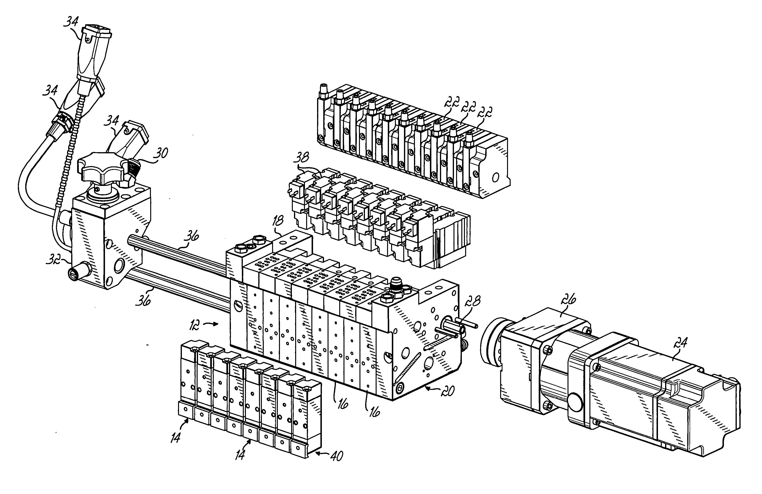
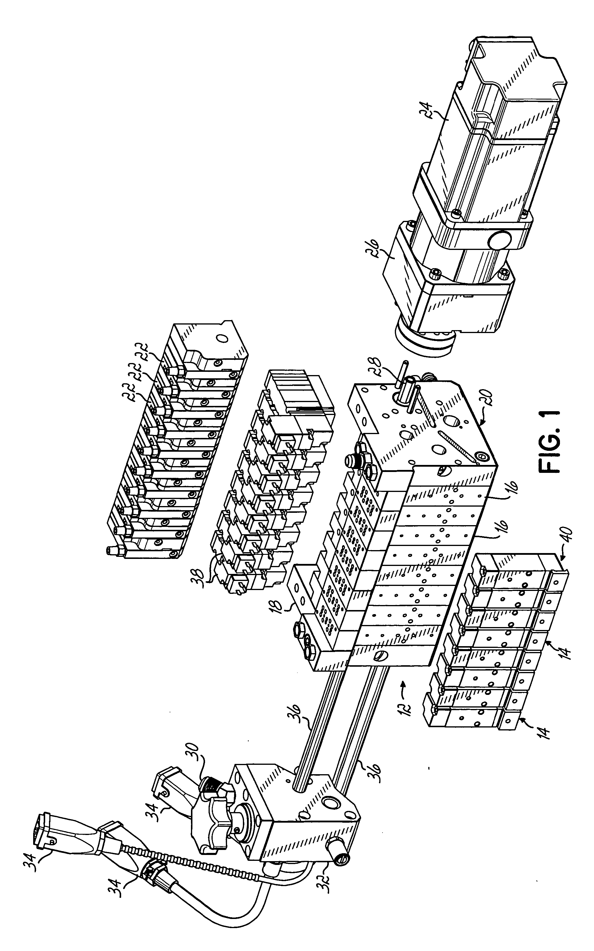
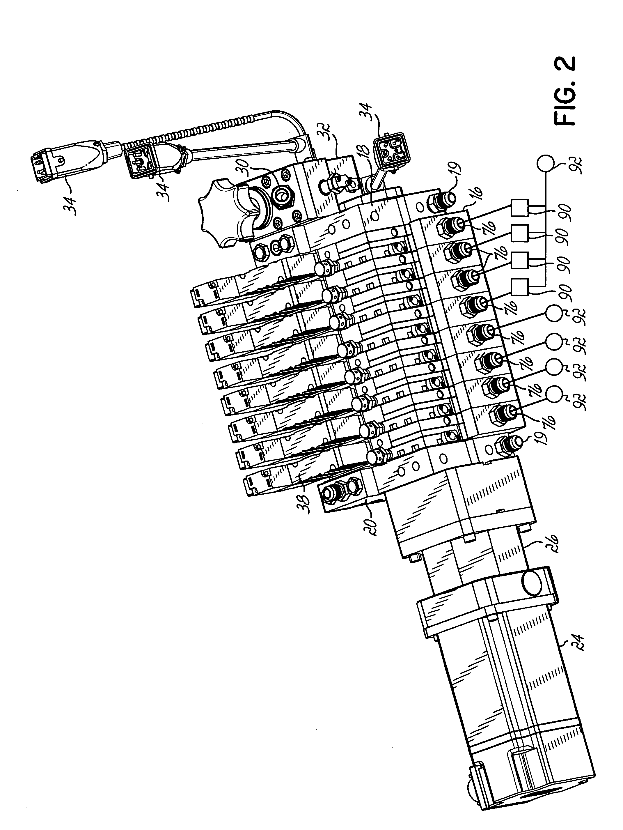
[0021]FIGS. 1 and 2 depict an exemplary metered liquid dispensing system 10 of the present invention, including a liquid dispensing applicator 12 having a plurality of dispensing modules 14. The applicator 12 is configured to individually meter the flow of liquid material through each module 14, whereby individually metered streams of liquid material may be dispensed to a substrate material. One such applicator particularly suited to this type of operation is the Universal Slice™ Applicator, available from Nordson Corporation of Westlake, Ohio and disclosed in U.S. Pat. No. 6,422,428, assigned to the assignee of the present invention, herein incorporated by reference in its entirety.

[0022] With continued reference to FIGS. 1 and 2, the applicator 12 includes several manifold segments 16 that are coupled together. Each manifold segment 16 is configured to supply liquid material to an individual module 14 that is coupled to the manifold segment 16. The manifold segments 16 are sandwi...


PUM

PropertyMeasurementUnit
pressureaaaaaaaaaa
flow rateaaaaaaaaaa
flexibilityaaaaaaaaaa

Abstract

A dispenser for dispensing liquid material while attenuating the liquid material or controlling the pattern of the liquid material with process air has a manifold with a plurality of process air passages for providing the process air to one or more liquid dispensing modules. The pressure of process air to one or more of the modules may be separately controlled to be different from the pressure provided to other modules on the dispenser. Accordingly, the air pressure provided to each module can be optimized to accommodate a particular dispensing die.

Description

FIELD OF THE INVENTION [0001] The present invention relates generally to liquid material dispensing systems, and more particularly to a liquid dispenser wherein process air to individual dispensing modules is separately controllable. BACKGROUND OF THE INVENTION [0002] Thermoplastic materials, such as hot melt adhesives, are used in a variety of applications including the manufacture of diapers, sanitary napkins, surgical drapes and various other products. The technology has evolved from the application of linear beads or fibers of material and other spray patterns, to air-assisted applications, such as spiral and melt-blown depositions of fibrous material. [0003] Often, the applicators will include one or more dispensing modules for applying the intended deposition pattern. Many of these modules include valve components that permit the modules to operate in an on / off fashion. One example of this type of dispending module is disclosed in U.S. Pat. No. 6,089,413, assigned to the assig...

Claims


Application Information

Patent Timeline
Patent Type & Authority Applications(United States)
IPC IPC(8): B05D1/26B05B7/00B05B7/08B05B7/24B05C5/00B05C5/02
CPCB05B7/0807B05B7/2486B05C5/027B05C5/001B05B7/2491F17D1/005
Inventor HARRIS, MICHAEL W.KLAUS, RICK J.
Owner NORDSON CORP
Why Eureka
Try Eureka