Bite valve

a valve and valve body technology, applied in the field of valves, can solve the problems of more effort being applied when sucking out liquid contained in liquid containers, etc., and achieve the effects of enhancing open status, reducing effort, and convenient dispensing

Inactive Publication Date: 2005-11-03
YANG SHIH SHENG
View PDF10 Cites 21 Cited by
  • Summary
  • Abstract
  • Description
  • Claims
  • Application Information

AI Technical Summary

Benefits of technology

[0008] The primary object of the invention is to provide a bite valve that enables a liquid contained in a liquid container to be more easily dispensed, thereby allowing a user to acquire the liquid in the liquid container with minimal effort during sports.
[0009] The secondary object of the invention is to provide a bite valve having an enhance open status when a liquid outlet slit thereof is compressed and a larger extended width of the liquid outlet slit thereof as well as offering greater tightening forces.
[0010] To accomplish the aforesaid objects, a bite valve according to the invention is manufactured from a soft and flexible material, and comprises a joining section and a liquid outlet section. The bite valve also has at least a pair of columns at an inner wall approaching the liquid outlet section, so as to prevent an inner channel from being closed when the bite valve is held between one's teeth. In addition, the columns also enable a plate body at two sides of a liquid outlet slit of the liquid outlet section to horizontally displace, such that upper and lower widths of the liquid outlet slit opened are even further expanded. The bite value further has an extension tube projecting from an outer periphery of the liquid outlet section, with the extension tube being capable of bending inward to accommodate around the outer periphery of the liquid outlet section, thereby tightly shutting the liquid outlet slit of the liquid outlet section. The joining section is provided with an inner screw thread at an interior thereof, so as to facilitate dispensing a liquid contained in a liquid container when the bite valve is joined with a liquid guide tube of the liquid container using the joining section thereof.

Problems solved by technology

As a result, more effort is necessarily applied when sucking out the liquid contained in the liquid container.

Method used


Image

  • Bite valve
  • Bite valve
  • Bite valve

Examples


Embodiment Construction

[0022] To better understand the invention, detailed descriptions shall be given with the accompanying drawings below.

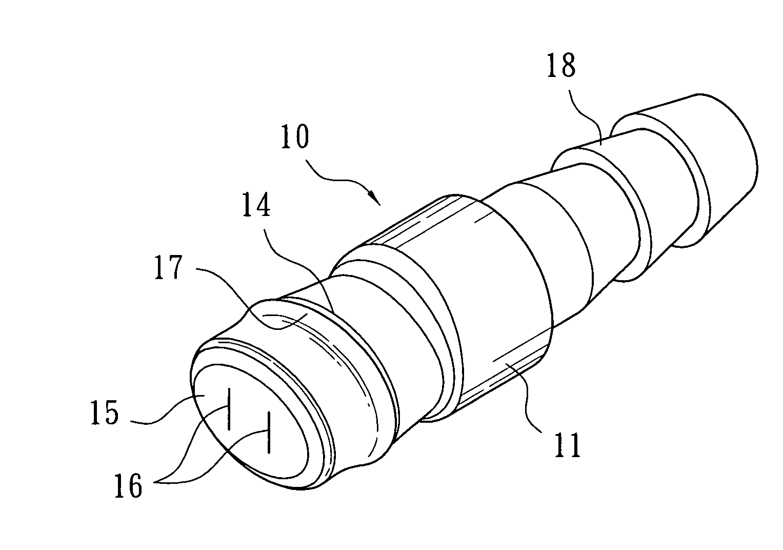
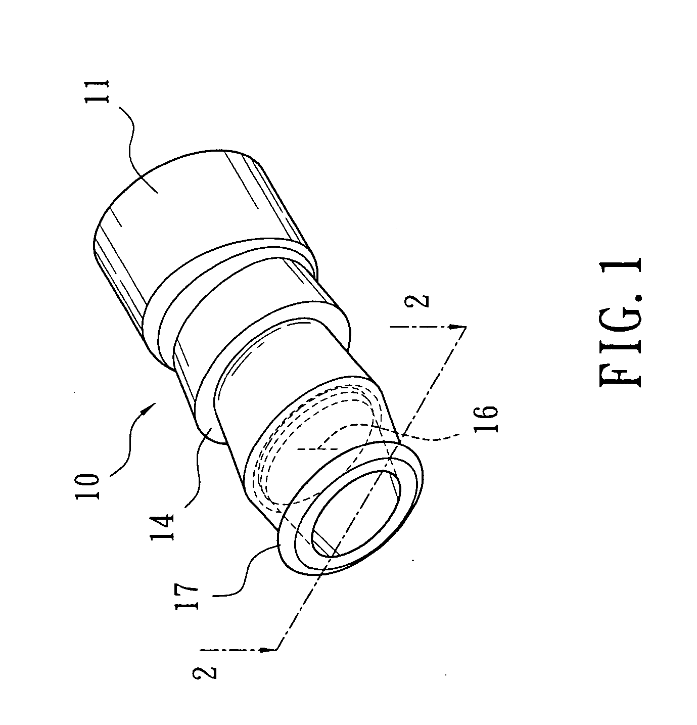
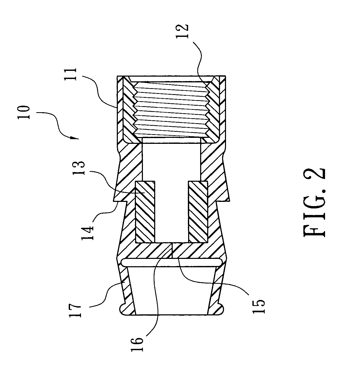
[0023] Referring to FIGS. 1 and 2, a bite valve 10 according to the invention is manufactured from a soft and flexible material; and comprises a joining section 11 at a rear portion thereof, a liquid outlet section 15 at a front portion thereof, a step section 14 at the liquid outlet section 15, an inner screw thread 12 at an inner wall of the joining section 11, a liquid outlet slit 16 penetrated through a vertical wall of the liquid outlet section 15, an extension tube 17 having a specific length extended from a side of the liquid outlet section 15 and a diameter gradually contracted, at least a pair of columns 13 at an inner wall thereof. Wherein, the columns 13 are disposed in pairs and are relatively located at two sides of the liquid outlet slit 16, and the step section 14 is provided at outer sides of the columns 13. In addition, for adapting to shapes of the ...


PUM


Abstract

A bite valve manufactured from a soft and flexible material includes a joining section, a liquid outlet section, and at least a pair of columns at an inner wall approaching the liquid outlet section to retain the bite valve and to prevent an inner channel of the bite valve from being closed, and an extension tube projecting from an outer periphery of the liquid outlet section and being capable of bending backward to accommodate around the outer periphery of the liquid outlet section. Wherein, the joining section is for joining with a liquid guide tube of a liquid container.

Description

BACKGROUND OF THE INVENTION [0001] (a) Field of the Invention [0002] The invention relates to a bite valve, and more particularly, to a flexible bite valve having an enhanced open state, such that when a liquid outlet section thereof receives forces, an open width of the liquid outlet is larger and a liquid outlet slit can be transversely expanded with an optimal breadth to facilitate dispensing of a liquid. When the forces applied are dismissed, the liquid outlet slit offers highly intensive closure effects for accomplishing sealing functions. The invention is suitable for applications of liquid containers used during outdoor sports. [0003] (b) Description of the Prior Art [0004] To fulfill water intake needs of athletes especially bikers and climbers under all circumstances during outdoor sports, liquid containers having a bite valve were designed and extensively used. [0005] Referring to prior flexible bite valves of liquid container disclosed by the U.S. Pat. Nos. 5,601,207, 5,7...

Claims


Application Information

Patent Timeline
Patent Type & Authority Applications(United States)
IPC IPC(8): A45F3/16B65D5/72B65D47/20F16K15/14
CPCA45F3/16F16K15/147B65D47/2031
Inventor YANG, SHIH-SHENG
Owner YANG SHIH SHENG
Why Eureka
Try Eureka