
Rotatable display apparatus

Active Publication Date: 2005-11-03
INTELPROPLIST
View PDF10 Cites 4 Cited by
  • Summary
  • Abstract
  • Description
  • Claims
  • Application Information

AI Technical Summary

Benefits of technology

[0015] An advantage of the present invention is that a number of different display panels can be selectively rotated, either manually or automatically, each of the panels having differing means for supporting different forms of graphic media material. The support member can preferably assume a number of geometric configurations. According to the herein described embodiments, the member is cubic in configuration, containing four (4) lateral or side display panels, but it should be understood that this number can easily be varied depending on the application. Furthermore, it will also become readily apparent that the herein described support member can assume a variety of shapes such as circular (e.g., cylindrical), rhombic, trapezoidal, triangular, other polyhedral configurations and the like. According to yet another preferred embodiment, the display panels can be directly and separately attached to the vertically extending pole wherein the pole can include a core portion having a configuration that permits attachment thereto. For example, the core portion can be square or round in cross section.
[0016] According to another embodiment, at least one of display panels can be separately hinged to the support member or directly to the vertically extending member, permitting the panels to open in a leaf-like fashion, and maximizing available display space in a small area.
[0017] A further advantage of the present invention is that the display apparatus can be made more efficiently with fewer parts than previously known versions. Moreover, the ability to rout electrical leads through the herein described display apparatus significantly expands the number of uses thereof.

Problems solved by technology

These displays typically include a single planar facing surface onto which any of the above items can be affixed, thereby taking up a considerable amount of floor space.
There are a number of deficiencies, however, that are found even in the latter apparatus design.
First, the use of the turntable and other components add to the overall weight and complexity of the apparatus, making the apparatus an expensive design in terms of both cost and manufacture.
Second, the incorporation of the turntable is a source of noise in terms of operation when the support member is actually rotated.

Method used


Image

  • Rotatable display apparatus
  • Rotatable display apparatus
  • Rotatable display apparatus

Examples


Embodiment Construction

[0024] The following description relates to a number of embodiments of a rotatable display apparatus or kiosk that is made in accordance with the present invention. Throughout the discussion that follows a number of terms are used such as “top”, “bottom”, “lateral”, “side” and the like. These terms are not intended to be over limiting of the present invention and are intended merely to provide a frame of reference with regard to the accompanying drawings.

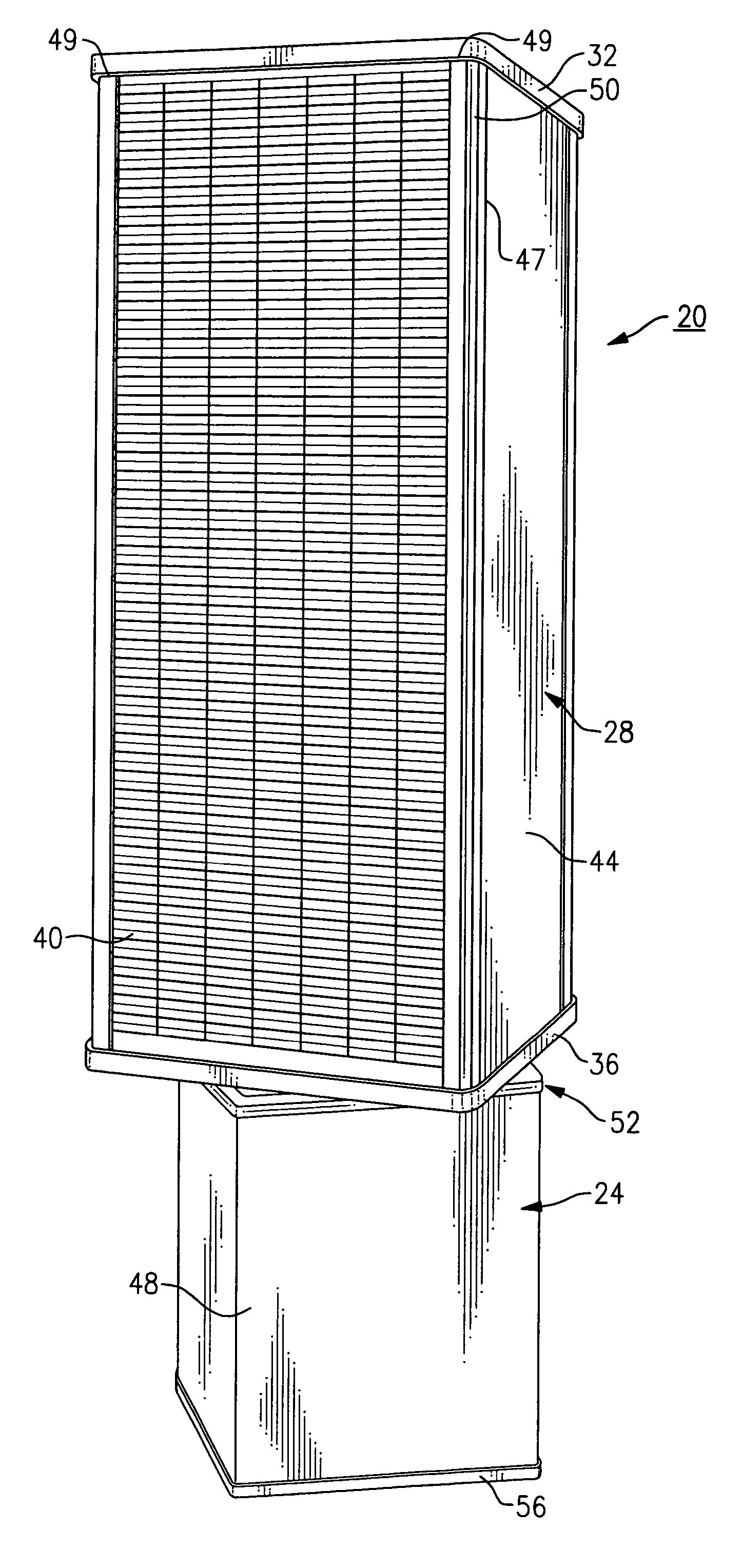
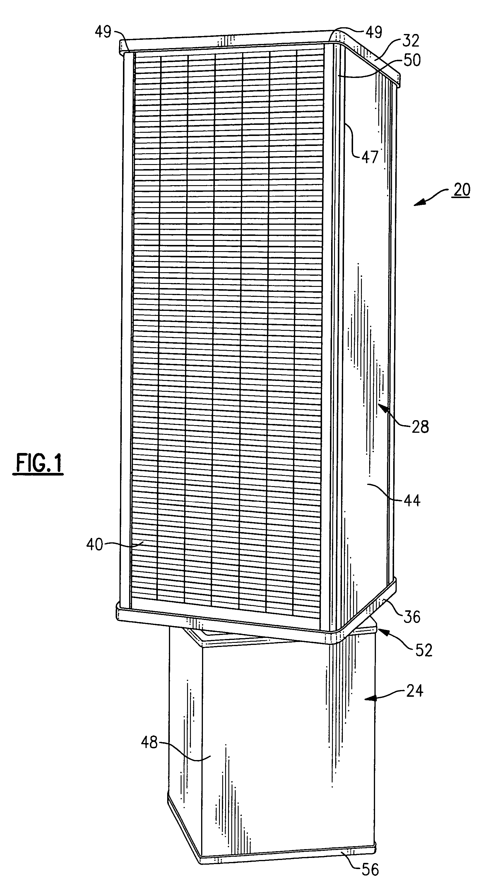
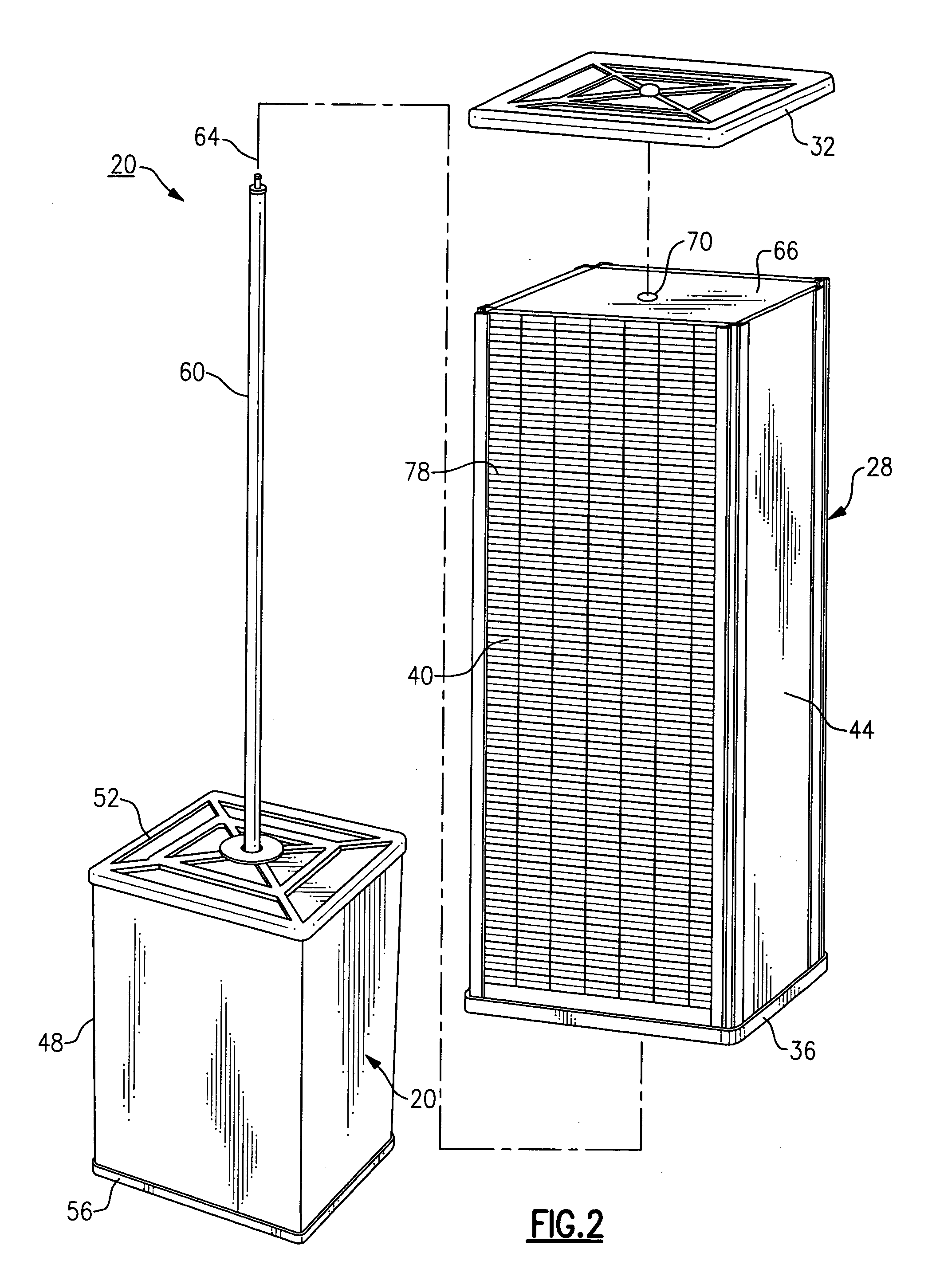
[0025] Referring to FIG. 1, the rotatable display apparatus 20 is defined by two primary components, namely a stationary or fixed base portion 24, as well as a support member 28 that is mounted onto the top of the stationary base portion and is supported for rotation thereupon, as described in greater detail below.

[0026] The support member 28, according to this embodiment, is cubic in configuration having an overall aspect ratio that includes height to width of approximately 4:1 in terms of height to width though this parameter ca...


PUM


Abstract

A display apparatus includes a stationary base portion and a support member mounted to a top surface of the stationary base portion. A vertically extending pole is disposed through the interior of each of the support member and the base portion along a center axis, thereby permitting selective rotation of the support member. The support member includes a plurality of lateral side panels for displaying graphic and or other materials, such as photographs and advertising. The vertically extending pole permits electrical leads to be routed therethrough to connect, for example, to at least one light source.

Description

FIELD OF THE INVENTION [0001] This invention relates to the field of displaying articles, and more specifically to a rotatable display apparatus that is capable of displaying or supporting a plurality of graphic and other media and / or advertising materials for display. BACKGROUND OF THE INVENTION [0002] It is known in the field to provide certain forms of display upon which graphic media materials such as articles, photographs, and other textual and / or pictorial items can be displayed or presented. Such displays have proven useful for groups or gatherings including, for example, weddings, bowling and golf tournaments and leagues, corporate functions and outings, and the like. These displays typically include a single planar facing surface onto which any of the above items can be affixed, thereby taking up a considerable amount of floor space. Such displays, to date, include apparatus such as bulletin boards and the like. Similar displays, used for example, for advertising or for fun...

Claims


Application Information

Patent Timeline
IPC IPC(8): A47F5/025A63K3/02F16M13/00G09G5/00
CPCA47F5/025
Inventor KRAPF, WALLACE A.ROSSBOROUGH, DANIEL W.
Owner INTELPROPLIST
Learn More