Human interfaces for homes, medical devices and vehicles

Inactive Publication Date: 2015-03-12
PRYOR TIMOTHY R
View PDF7 Cites 49 Cited by
  • Summary
  • Abstract
  • Description
  • Claims
  • Application Information

AI Technical Summary

Benefits of technology

[0020]It is a goal of the invention to provide method and apparatus, which can be resistant to damage by use of hard, flexible, or otherwise suitable materials for the screen/control surface.
[0021]It is an addition

Problems solved by technology

This device utilizes radiation from a large group of expensive UV LEDs to traverse the active display material which can cause degradation problems and warranty issues

Method used


Image

  • Human interfaces for homes, medical devices and vehicles
  • Human interfaces for homes, medical devices and vehicles
  • Human interfaces for homes, medical devices and vehicles

Examples


Example

[0070]My application Ser. No. 12 / 748,666, of which this application is a continuation-in-part, discloses in FIG. 17 thereof a new form of easily sterilizable and cleanable control device for use in hospitals and nursing homes. The complete separation of the items contacted by persons from the operating electronics allows knobs and other physical controls and the touch screen to be easily cleaned or sterilized without harming the electronics or voiding the warranty thereof.

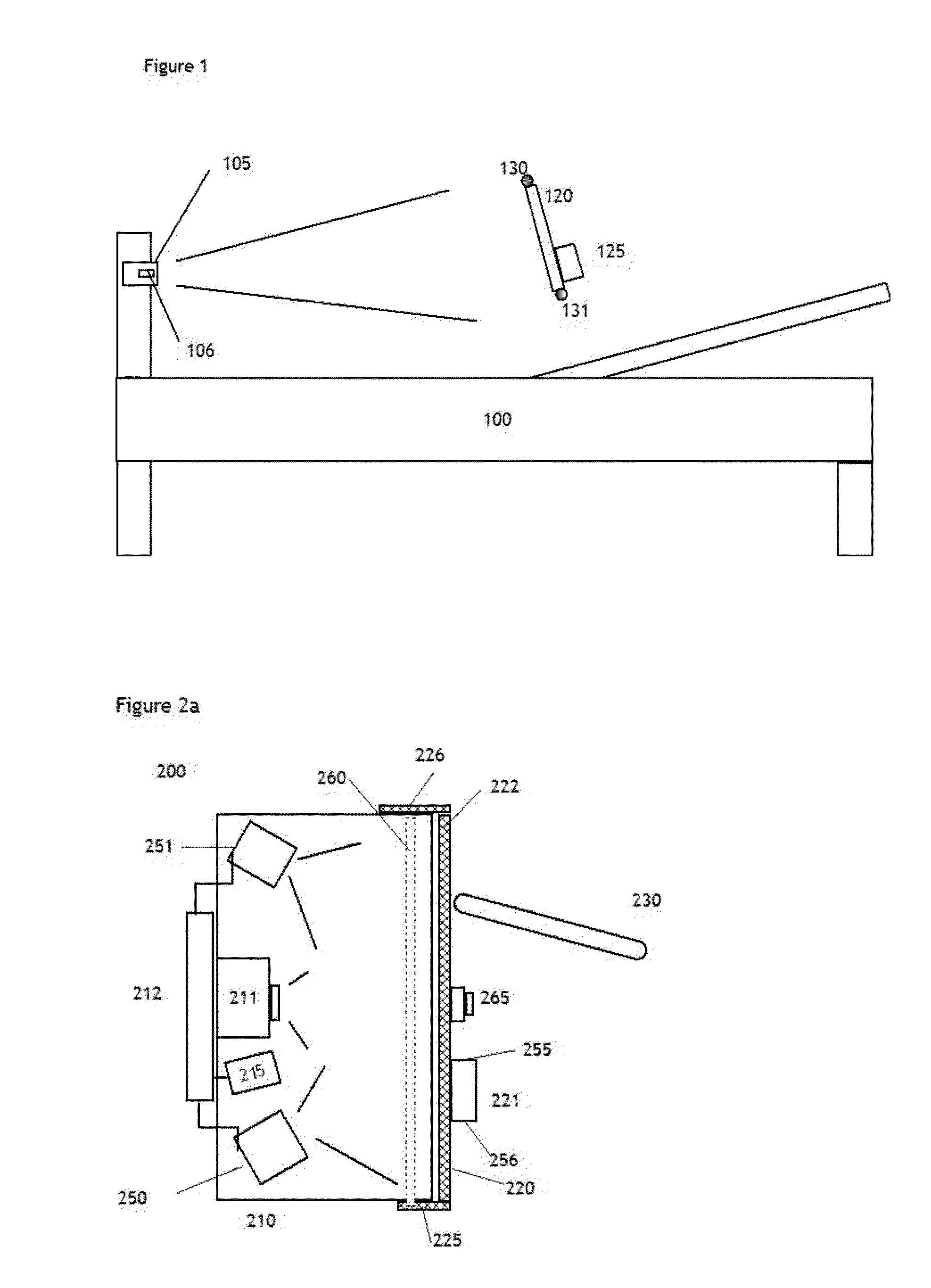
[0071]FIG. 1 illustrates a similar embodiment which makes use of the unique ability of the invention to have an easy to clean and even sterilize-able screen and control surface 120, in this case for use in a hospital bed 100. As shown the projector & sensor module 105 which includes camera 106 if a separate camera is required, is located at the foot of the bed, or alternatively in other locations such as the side of the bed, and illuminates and views the screen and control surface from the rear. A computer not show...


PUM


Abstract

Disclosed are novel method and apparatus for monitoring and aiding persons in vehicles and at home, especially senior citizens and others whose capabilities may be diminished. Electro-optical sensing of both person's body portions and physical controls is utilized, following from both disclosure on my RTD (Reconfigurable Tactile Display) invention as well as other gesture and motion based inventions in regard to sensing of control inputs from physical control (e.g. knobs, switches) positions and persons gestures. Applications to vehicles and the home are disclosed as well as applications to areas such as operating rooms and other locations in the hospital where sterility is paramount. A unique self-sterilizing control panel is also disclosed.

Description

CROSS-REFERENCE TO RELATED APPLICATIONS[0001]The disclosures of the following patent applications are incorporated by reference in their entirety: U.S. provisional application 61 / 842,340, filed Jul. 2, 2013; U.S. patent application Ser. No. 12 / 748,666, filed Mar. 29, 2010; U.S. patent application Ser. No. 11 / 832,134, filed Aug. 1, 2007; U.S. provisional application 60 / 835,072, filed Aug. 3, 2006; U.S. patent application Ser. No. 11 / 349,350, filed Feb. 8, 2006; U.S. patent application Ser. No. 11 / 319,807 (now U.S. Pat. No. 7,671,851), filed Dec. 29, 2005; U.S. patent application Ser. No. 11 / 184,076 (now U.S. Pat. No. 7,466,843), filed Jul. 19, 2005; U.S. patent application Ser. No. 11 / 045,131, filed Jan. 31, 2005; U.S. patent application Ser. No. 10 / 934,762 (now U.S. Pat. No. 8,287,374), filed Sep. 7, 2004; PCT / US04 / 09701, filed Mar. 31, 2004; U.S. patent application Ser. No. 10 / 611,814 (now U.S. Pat. No. 7,489,303), filed Jul. 2, 2003; U.S. patent application Ser. No. 09 / 789,538 (no...

Claims


Application Information

Patent Timeline
IPC IPC(8): G06F3/042A61L2/10G06F3/0488G06F3/0354G06F3/03
CPCG06F3/0425G06F3/03547G06F3/0308G06F2203/04808A61L2/10G06F2203/04104G06F3/04883A61L2202/14G06F3/042B60K2370/146H04N23/63G06V20/56B60K35/00B60R1/00B60R2300/802G06F3/011G06T7/20H04N7/183
Inventor PRYOR, TIMOTHY R.
Owner PRYOR TIMOTHY R
Why Eureka
Try Eureka