Fuel tank with improved creep resistance and method for manufacturing it

a fuel tank and creep resistance technology, applied in the field of fuel tanks with improved creep resistance, can solve problems such as internal reinforcement breakage, and achieve the effect of limiting damage to the fuel tank, distributing stress without increasing the deformation of the tank, and reducing the damage to the tank

Active Publication Date: 2013-01-10
PLASTIC OMNIUM ADVANCED INNOVATION & RES SA
View PDF2 Cites 9 Cited by
  • Summary
  • Abstract
  • Description
  • Claims
  • Application Information

AI Technical Summary

Benefits of technology

[0014]The present invention aims at solving these problems by providing a reinforcement which is such that it allows a better distribution of the stresses without increasing the tank deformation while under pressure. The invention also allows to add flexibility in the event of crash allowing to limit damages to the fuel tank.

Problems solved by technology

Although the solution set forth above can work in some circumstances, there are nevertheless specific cases in which it can lead to problems owed to the fact that the top and bottom of the tank are not parallel due to :blow molding tolerances;deformations during part cooling;deformations during thermal expansion;deformations of tank shells not identical in top and bottom tank surface;a specific non-parallel design of the top surface and the bottom surface of the tank.
More specifically, since no movement between the two opposite tank surfaces is allowed (this design not allowing any misalignment of the linked surfaces), all stresses are taken by the reinforcing element which in certain cases could create too high stress concentrations leading to break of the internal reinforcement after a long pressurized situation.

Method used


Image

  • Fuel tank with improved creep resistance and method for manufacturing it
  • Fuel tank with improved creep resistance and method for manufacturing it
  • Fuel tank with improved creep resistance and method for manufacturing it

Examples


first embodiment

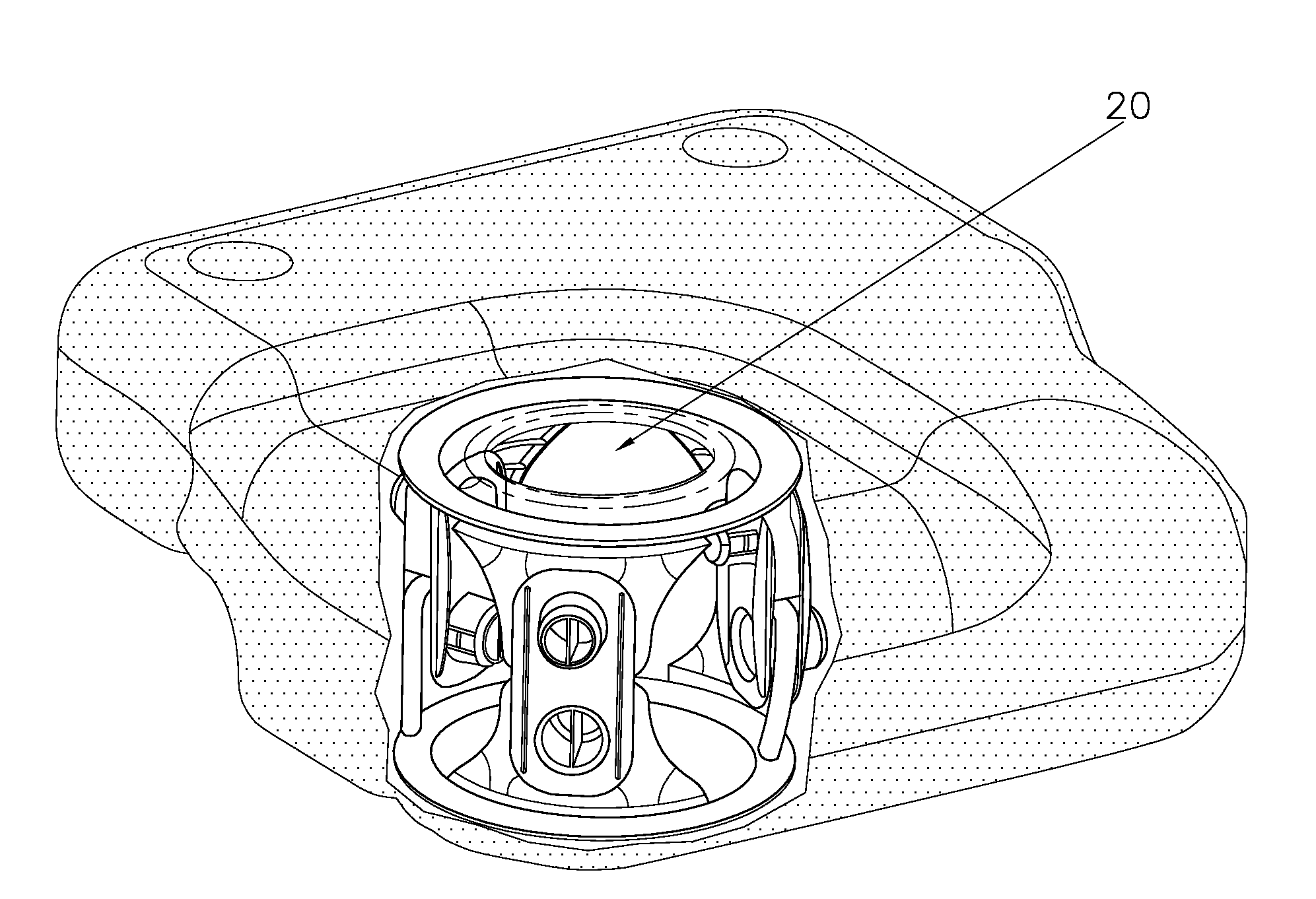
[0041]In a first embodiment, the tank is molded first, then, an opening is made into its wall (which generally is the service opening through which functional elements like the fuel sender unit are introduced) and then, the completely assembled reinforcing element (the two parts with their rotation link or articulation) is fitted inside a portion in relief or shape (like a dove tail for instance) in the tank wall portions.

[0042]In this embodiment, the method generally comprises:[0043]the tank is molded with a portion or shape in relief in its two portions[0044]an opening is made into the tank wall[0045]the completely assembled reinforcing element is fixed inside the portions or shapes in relief.

second embodiment

[0046]In a second embodiment, which is preferred, at least one of the two parts of the reinforcing element is fixed to the tank wall during the molding of the tank.

[0047]In that embodiment, the process of the invention preferably comprises the following steps:[0048]1. a plastic parison comprising two distinct parts is inserted into an open two-cavity mold;[0049]2. a core is inserted inside the parison, said core bearing at least one of the two parts of the reinforcing element;[0050]3. the parison is pressed firmly against the mold cavities (generally by blowing through the core and / or creating suction behind the cavities);[0051]4. the at least one part of the reinforcing element is fixed at one of the two locations of the parison using the core;[0052]5. the core is withdrawn;[0053]6. the mold is closed again, bringing its two cavities together in such a way as to grip the two parts of the parison around their periphery in order to weld them together;[0054]7. a pressurized fluid is i...


PUM

PropertyMeasurementUnit
temperatureaaaaaaaaaa
mechanicalaaaaaaaaaa
elastic partaaaaaaaaaa

Abstract

A fuel tank having two opposite wall portions and at least one reinforcing element connecting these two wall portions, such reinforcing element comprising at least two parts linked by at least one rotating link. A method for manufacturing such tank.

Description

CROSS-REFERENCE TO RELATED APPLICATIONS[0001]This application claims priority to U.S. provisional application No. 61 / 490,054, filed on May 25, 2011 and to European application No. 11172988.5 filed on Jul. 7, 2011, the whole content of these applications being incorporated herein by reference for all purposes.TECHNICAL FIELD OF THE INVENTION[0002]The present invention relates to a fuel tank with improved creep resistance, and to a method for manufacturing it.BACKGROUND[0003]Fuel tanks intended for motor vehicles, especially plastic fuel tanks, have to meet specifications that specify maximum permissible amplitudes of deflection on their lower skin. The deflections stated in these specifications usually have to be met during ageing tests in which the tank contains a certain quantity of fuel for a given period of time (typically several weeks) and at temperature (usually 40° C.). The purpose of these specifications is to ensure that vehicles maintain their road clearance and to prevent...

Claims


Application Information

Patent Timeline
Patent Type & Authority Applications(United States)
IPC IPC(8): B29C51/06B23P11/00B23P17/00B60K15/03
CPCB60K15/03006Y10T29/49826Y10T29/4998B60K15/03177B60K2015/03328B60K2015/03375
Inventor HILL, DAVIDCRIEL, BJORNCUVELIER, VINCENTMCCLEARY, SCOTT
Owner PLASTIC OMNIUM ADVANCED INNOVATION & RES SA
Why Eureka
Try Eureka