Grid for radiography and manufacturing method thereof, and radiation imaging system

a radiography and grid technology, applied in the field of grid for radiography, and the manufacturing method of the grid, can solve the problems of difficult handling of sheets, inability to neatly laminate sheets without gaps, and inability to detect the vignetting of x-rays, so as to prevent diffusion and improve the grid performance. , the effect of high grid performan

Inactive Publication Date: 2012-05-31
FUJIFILM CORP
View PDF0 Cites 10 Cited by
  • Summary
  • Abstract
  • Description
  • Claims
  • Application Information

AI Technical Summary

Benefits of technology

[0021]According to the grid of the present invention, the buffer layer is provided between the radiation absorbing portion and the radiation transparent portion, and bonds them. The buffer layer absorbs stress occurring in the grid, when the grid is curved into a convergence structure. This prevents the breakage of the grid, such as unstuck between the radiation absorbing portion and the radiation transparent portion, and a crack of the grid. The buffer layer also prevents the diffusion of the radiation absorbing portions into the radiation transparent portions by reaction of heat, when the grid is heated by irradiation with the radiation. Therefore, the boundaries between the X-ray absorbing portions and the X-ray transparent portions do not become unclear, and high grid performance is maintained.
[0022]Also, since the buffer layer composes a part of the radiation transparent portion or the radiation absorbing portion, the provision of the buffer layer does not degrade the grid performance.
[0023]Furthermore, the radiation absorbing portions, the radiation transparent portions, and the buffer layer are inclined so as to converge into the radiation source from which the radiation is emitted, and has a width gradually increasing from the first surface on the side of the radiation source to the second surface opposite to the first surface. Thus,

Problems solved by technology

Thus, if the size of the grid is increased, the vignetting of the X-rays becomes a problem in a peripheral portion of the grid.
The method described in the Japanese Patent Laid-Open Publication No. 2009-240378, however, has a problem of difficulty in handling the sheets, because the extremely thin sheets with a thickness of several micrometers have to be laminated.
If the sheets kink, bend, or sag when being laminated, for example, the sheets cannot be neatly laminated without a gap.
In such a case, the X-ray absorbing portions and the X-ray transparent portions have irregular widths and pitches

Method used


Image

  • Grid for radiography and manufacturing method thereof, and radiation imaging system
  • Grid for radiography and manufacturing method thereof, and radiation imaging system
  • Grid for radiography and manufacturing method thereof, and radiation imaging system

Examples


first embodiment

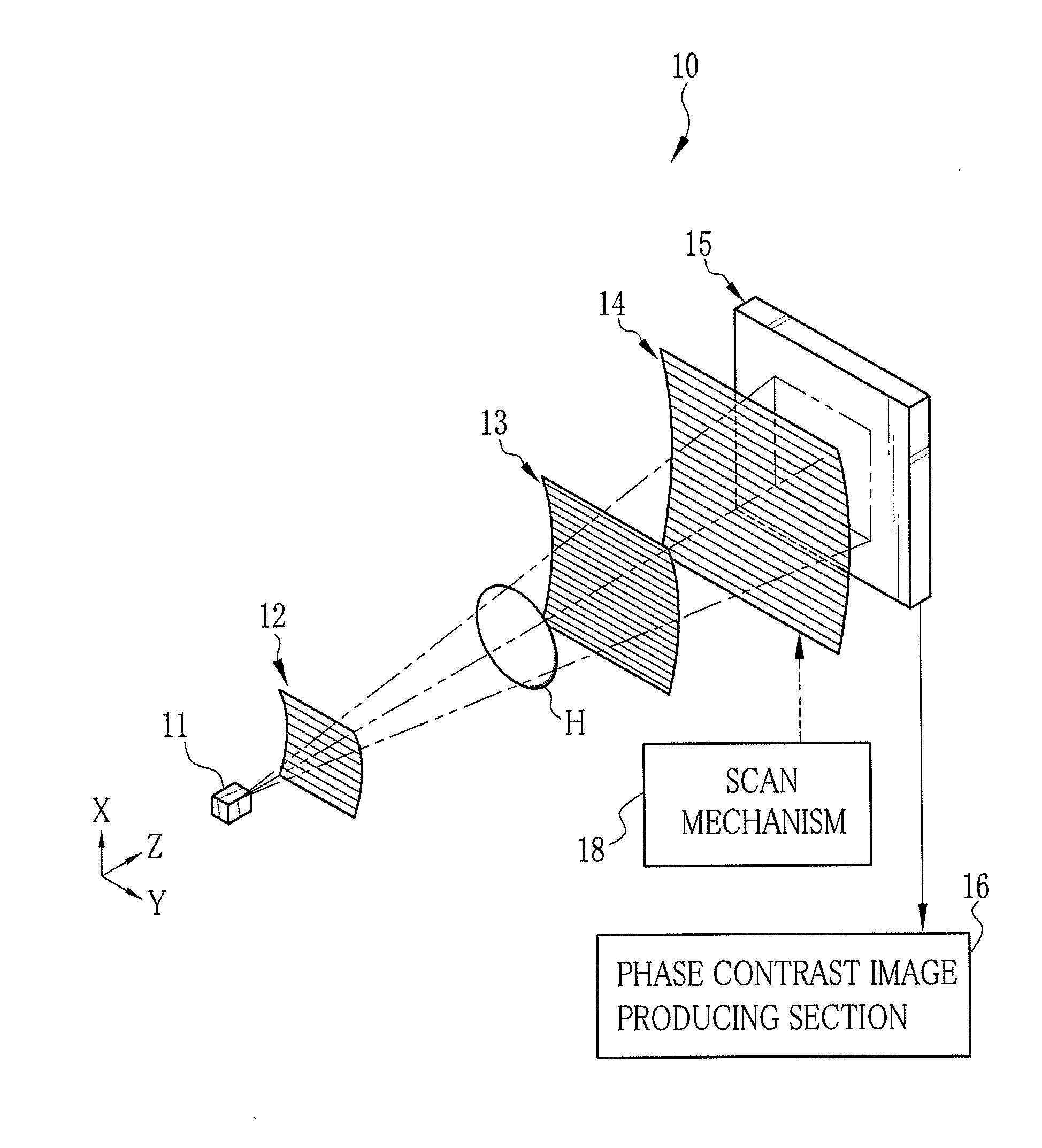
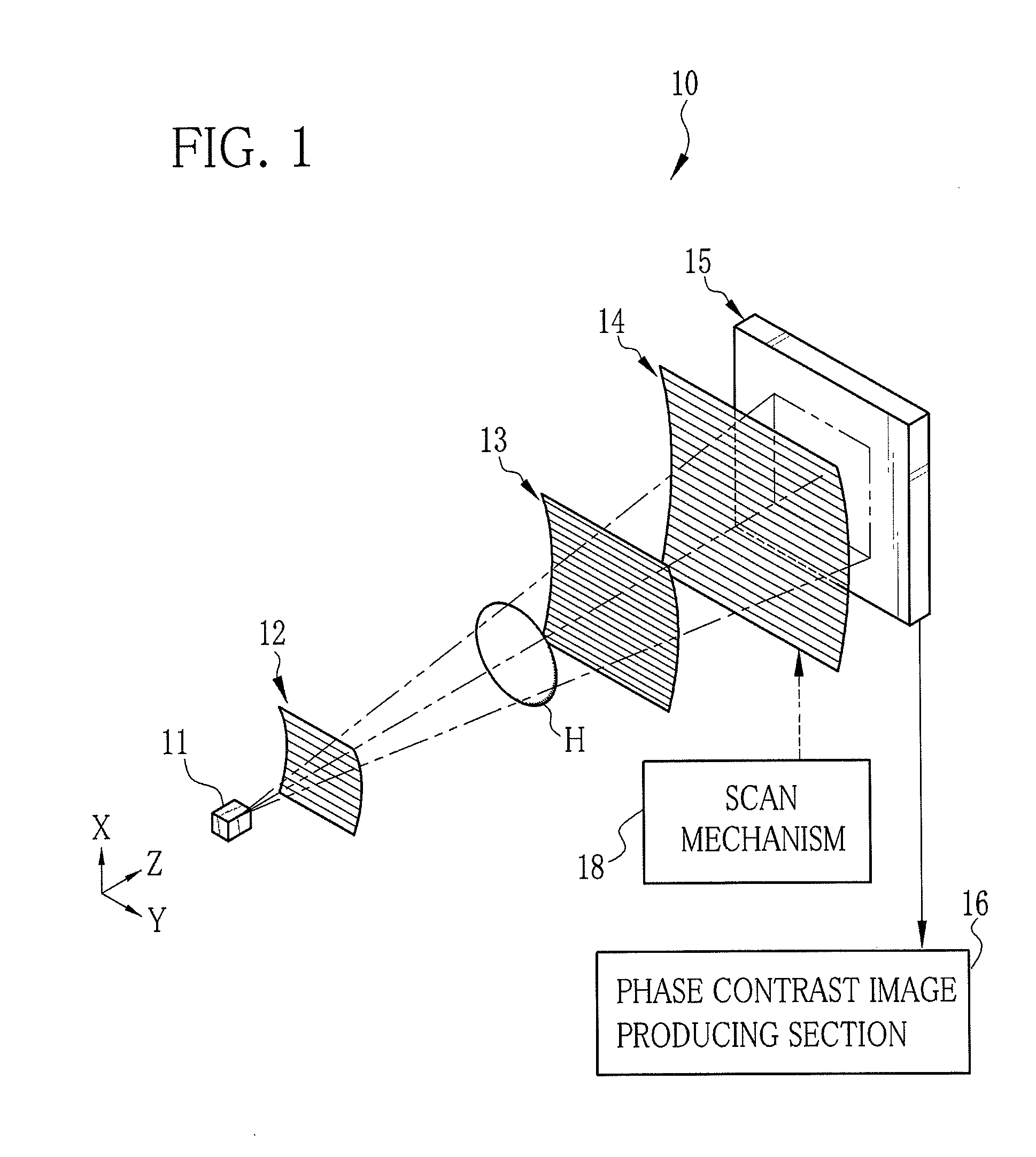
[0044]As shown in FIG. 1, an X-ray imaging system 10 is constituted of an X-ray source 11, a source grid 12, a first grid 13, a second grid 14, and an X-ray image detector 15 that are arranged in a Z direction being an X-ray propagation direction. The X-ray source 11 has, for example, a rotating anode type X-ray tube and a collimator for limiting an irradiation field of X-rays, and applies a cone beam of X-rays to a sample H. The X-ray image detector 15 is a flat panel detector (FPD) composed of semiconductor circuitry, for example, and is disposed behind the second grid 14. The X-ray image detector 15 is connected to a phase contrast image producing section (computing section) 16, which produces a phase contrast image from image data detected by the X-ray image detector 15.

[0045]The source grid 12, the first grid 13, and the second grid 14 are X-ray absorption grids, and are opposed to the X-ray source 11 in the Z direction. The first grid 13 is disposed at a certain distance away ...

second embodiment

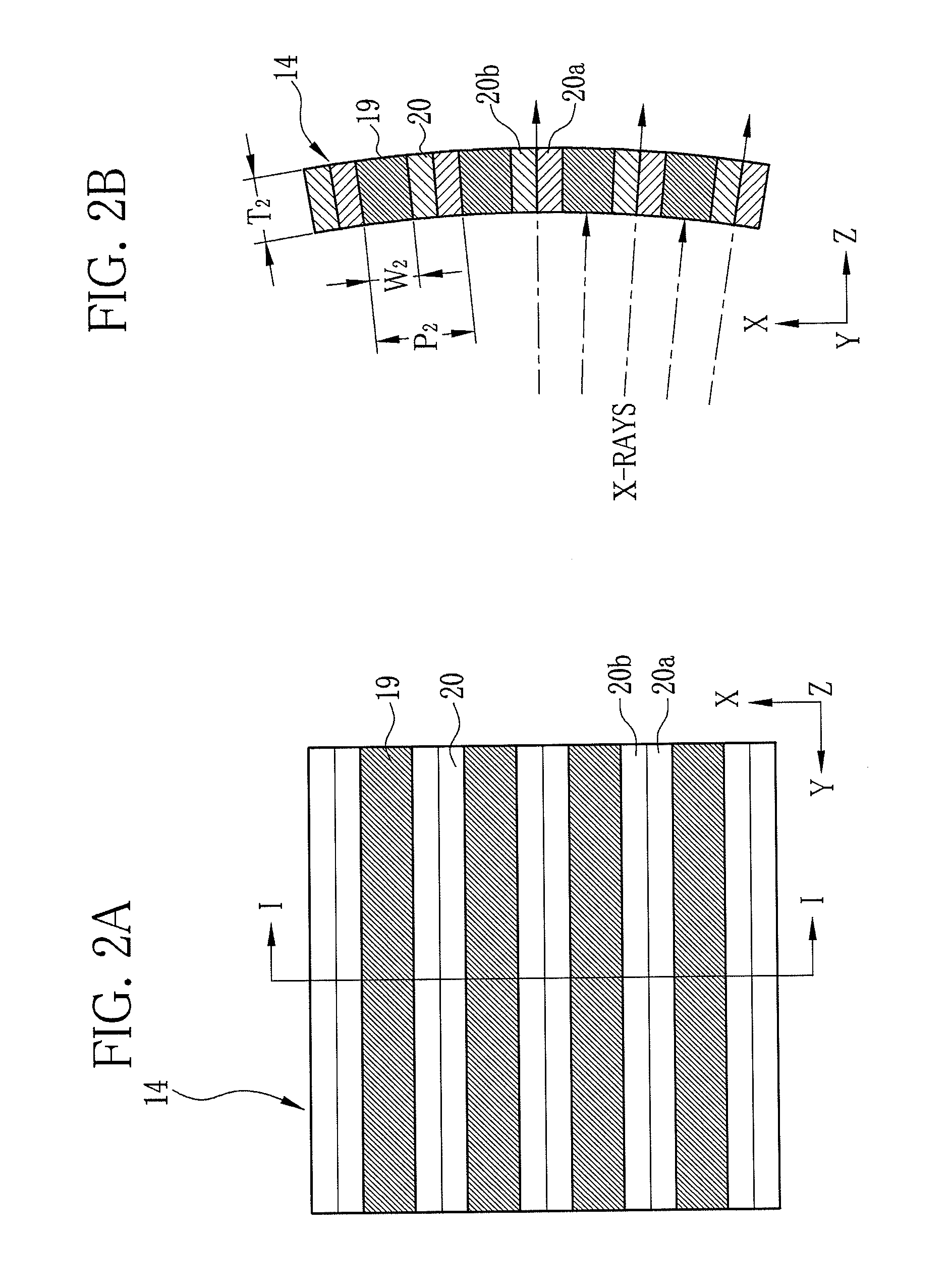
[0070]In the above first embodiment, the X-ray transparent portion 20 is composed of the X-ray transparent sheet 20a and the buffer layer 20b. However, as shown in a second grid 40 of FIGS. 8A and 8B, an X-ray absorbing portion 41 may be composed of the X-ray absorbing layer 22 and a buffer layer 42, instead. In this case, an X-ray absorbing material made of gold, platinum, silver, or lead is dispersed into an adhesive for forming the buffer layer 42, in order to impart the X-ray absorptivity to the buffer layer 42. The X-ray transparent sheet 20a is formed so as to have a thickness corresponding with the thickness of an X-ray transparent portion 43. The sum of the thicknesses of the X-ray absorbing layer 22 and the buffer layer 42 corresponds with the thickness of the X-ray absorbing portion 41. The second grid 40 of the second embodiment has the same structure as the second grid 14 of the first embodiment except for the layer structure of the X-ray absorbing portions 41 and the X-...

third embodiment

[0072]In the above embodiments, the grid with the convergence structure is formed by curving the layer laminated sheet 29 sliced out of the roll, but a flat grid with the convergence structure may be formed. A third embodiment of the present invention will be hereinafter described. In the following description, the reference numerals same as those of the first and second embodiments refer to the same components, and detailed description thereof will be omitted.

[0073]As shown in FIGS. 9A and 9B, a second grid 50 according to the third embodiment has the plural X-ray absorbing portions 19 and the plural X-ray transparent portions 20 that extend in the Y direction and are arranged alternately in the X direction. The X-ray transparent portion 20 is composed of the X-ray absorbing sheet 20a and the buffer layer 20b. The second grid 50 has the convergence structure in which the X-ray absorbing portions 19 and the X-ray transparent portions 20 are inclined in the YZ plane so as to converge...


PUM

PropertyMeasurementUnit
Thicknessaaaaaaaaaa
Shapeaaaaaaaaaa
Transparencyaaaaaaaaaa

Abstract

In a manufacturing process of a second grid, an X-ray absorbing layer is formed on a top surface of a strip of X-ray transparent sheet during conveyance, and a buffer layer is formed on a rear surface thereof. After that, the X-ray transparent sheet is wound into a roll so as to expose the X-ray absorbing layer to outside. Thus, the X-ray transparent sheet and the X-ray absorbing layer are laminated with being bonded with the buffer layer. The roll of layer laminated structure is sliced in its radial direction into a layer laminated sheet, which has the buffer layer, the X-ray transparent sheet, and the X-ray absorbing layer laminated in layers. After polishing sliced surfaces of the layer laminated sheet, the layer laminated sheet is pressed by a pressing device, so the second grid is curved into an approximately cylindrical shape.

Description

BACKGROUND OF THE INVENTION[0001]1. Field of the Invention[0002]The present invention relates to a grid for radiography, and a manufacturing method of the grid, and a radiation imaging system using the grid.[0003]2. Description Related to the Prior Art[0004]When radiation, for example, X-rays are incident upon an object, the intensity and phase of the X-rays are changed by interaction between the X-rays and the object. At this time, it is known that the phase change of the X-rays is larger than the intensity change. Taking advantage of these properties of the X-rays, X-ray phase imaging is developed and actively researched. In the X-ray phase imaging, a high-contrast image (hereinafter called phase contrast image) of a sample is obtained based on the phase change (angular change) of the X-rays caused by the sample, even if the sample has low X-ray absorptivity.[0005]There is devised an X-ray imaging system that carries out the X-ray phase imaging using the Talbot effect, which is pr...

Claims


Application Information

Patent Timeline
IPC IPC(8): G01N23/20B32B37/02B32B38/00B32B37/12B32B37/14B32B38/10G21K1/02B32B37/10
CPCB32B33/00G21K1/025Y10T156/1052G21K2207/005Y10T156/1051G21K1/06
Inventor KANEKO, YASUHISA
Owner FUJIFILM CORP
Why Eureka
Try Eureka