Method and IC driver for series connected R, G, B LEDs

Active Publication Date: 2005-11-03
ANALOG DEVICES INC
View PDF37 Cites 294 Cited by
  • Summary
  • Abstract
  • Description
  • Claims
  • Application Information

AI Technical Summary

Benefits of technology

[0016] Another object of the present disclosure is to provide an efficient LED driver for producing white light using a set of series connected RGB LEDs.
[0017] Another o

Problems solved by technology

However, regardless of the particular circuit configuration for energizing parallel connected WLEDs 66, the ballast resistors 74 always waste power.
Consequently, circuits such as that depicted in FIG. 1 having WLEDs

Method used


Image

  • Method and IC driver for series connected R, G, B LEDs
  • Method and IC driver for series connected R, G, B LEDs
  • Method and IC driver for series connected R, G, B LEDs

Examples


Embodiment Construction

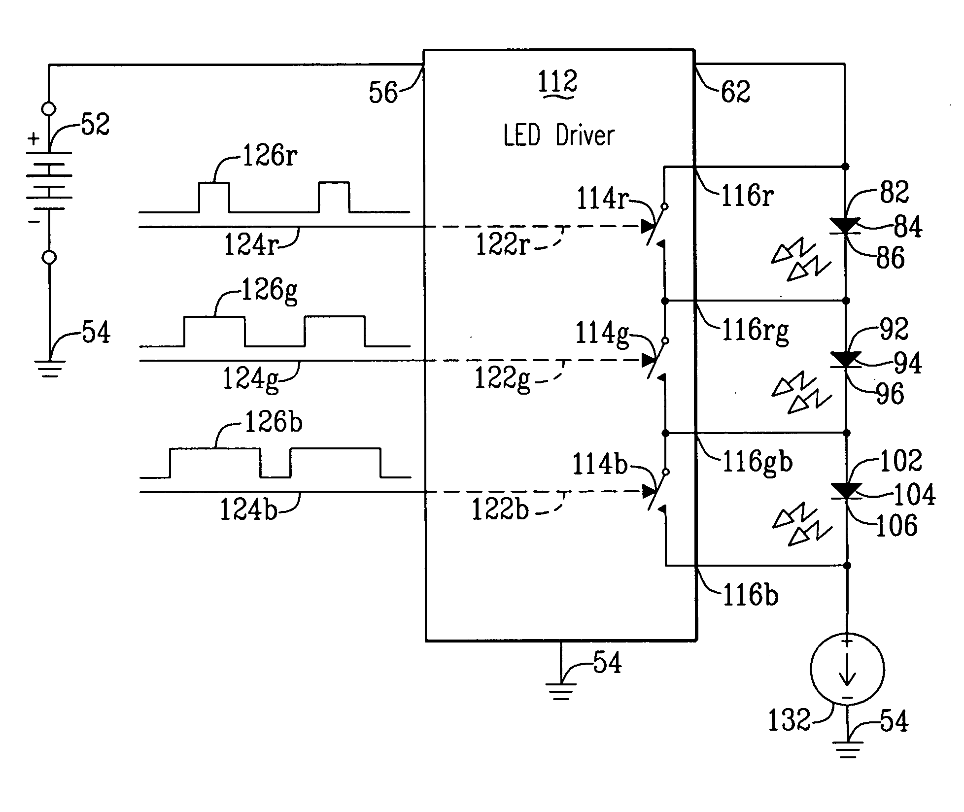
[0046] The present invention exploits the fact that power dissipated respectively in individual RGB LEDs 84, 94, 104 controls color and brightness of light emitted respectively from each of the LEDs. That is, not current flowing through a LED and not voltage applied across a LED, but a product of current times voltage, i.e. power, over a certain interval of time determines the color and brightness of light emitted from the individual RGB LEDs 84, 94, 104.

[0047] As depicted in FIG. 5, RGB LEDs 84, 94, 104 energized in accordance with the present disclosure are connected in series to reduce power loss. To allow differing power dissipation in each of the RGB LEDs 84, 94, 104 over a certain interval of time, a LED driver 112 in accordance with the present disclosure, preferably an IC, includes three (3) LED switches 114r, 114g, 114b. The LED switches 114r, 114g, 114b connect respectively in parallel with each of the RGB LEDs 84, 94, 104 via output terminals 116r, 116rg, 116gb, 116b of ...


PUM


Abstract

A LED driver is connectible to several series connected RGB LEDs which connect in series with a current generator. A plurality of LED switches are respectively connectible across one RGB LED. Each LED switch, operating in response to a binary signal is either open to permit electrical current to flow through the RGB LED, or closed to shunt current around that RGB LED. By varying respective duty cycles of the binary signals the LED driver is adapted for controlling operation of the combined RGB LEDs so they emit differing colors of light. An adaptive boost converter LED driver continuously adjusts voltage applied across the series connected RGB LEDs to be only that required for operating those LEDs through which open LED switches permit current to flow.

Description

CLAIM OF PROVISIONAL APPLICATION RIGHTS [0001] This application claims the benefit of U.S. Provisional Patent Application No. 60 / 567,343 filed on Apr. 30, 2004.BACKGROUND [0002] 1. Technical Field [0003] The present disclosure relates generally to electronic circuits for controlled energizing of light emitting diodes (“LEDs”), and more specifically for such circuits for controlled energizing of series connected red, green, blue (“RGB”) LEDs. [0004] 2. Description of the Prior Art [0005] One of the most important functions in various portable devices such as personal digital assistants (“PDAs”), cell phones, digital still cameras, camcorders, etc. is displaying to a user the device's present condition, i.e. a display function. Without a display function, a device's user could not enter data into or retrieve data from the device, i.e. control the device's operation. Thus, a portable device's display function is essential to its usefulness. [0006] Devices implement their display functi...

Claims


Application Information

Patent Timeline
IPC IPC(8): G09G3/14H05B44/00
CPCG09G3/3413H05B33/0857H05B33/083H05B33/0815H05B45/48H05B45/20H05B45/38H05B45/10
Inventor NEGRU, SORIN LAURENTIU
Owner ANALOG DEVICES INC
Why Eureka
Try Eureka