Image display device

a technology of image display device and display screen, which is applied in the field of display device, can solve the problems of device size and weight, and achieve the effects of reducing the size and weight of the device itself, reducing the cost, and maintaining the brightness and image quality performance of the image display devi

Inactive Publication Date: 2005-11-03
MAXELL HLDG LTD
View PDF15 Cites 5 Cited by
  • Summary
  • Abstract
  • Description
  • Claims
  • Application Information

AI Technical Summary

Benefits of technology

[0018] Methods to reduce the size and weight of the device itself, and lower the cost while maintaining the brightness and image quality performance of the image display device are therefore a problem in the above described technology of the related art. In other words, the optical efficiency of the dichroic prism constituting the color separating / combining means and the polarized beam splitter must be improved, and a method for inputting and outputting light to a reflective panel contrived and respective effective placement contrived in order to improve the image contrast and brightness, reduce the size of the device itself, reduce the weight and lower the cost.
[0019] In view of the above problems with the related art, it is an object of the invention to provide image display technology that is compact and inexpensive while maintaining brightness and high image quality.

Problems solved by technology

Methods to reduce the size and weight of the device itself, and lower the cost while maintaining the brightness and image quality performance of the image display device are therefore a problem in the above described technology of the related art.

Method used


Image

  • Image display device
  • Image display device
  • Image display device

Examples


first embodiment

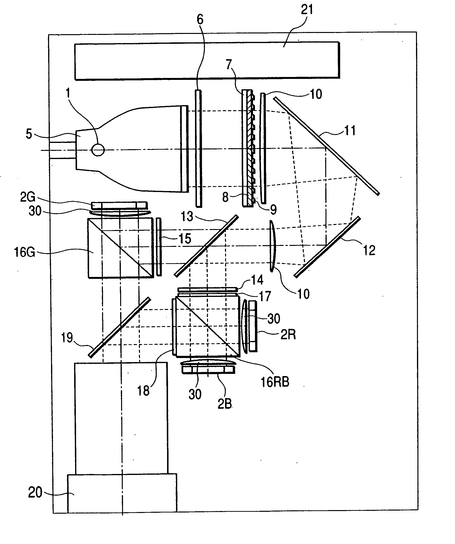
[0054] An overall plan view showing the projection is shown in FIG. 1. The embodiment in FIG. 1 shows three plate type projection display devices utilizing a total of three plates for the three primary colors R (red), G (green) and B (blue) constituted by reflective liquid crystal elements 2 as the liquid crystal light valves.

[0055] The projection display device in FIG. 1 contains a light source 1. The light source 1 is a white color lamp such as an ultra high voltage mercury lamp, metal halide lamp, xenon lamp, mercury xenon lamp or halogen lamp, etc. The light source 1 contains at least one reflective mirror 5 having a circular or polygonal output beam aperture and the light output from the light source 1 passes through the reflective liquid crystal elements 2 constituting the liquid crystal light valves, progresses to the projection lens 3 and is projected onto the screen 4.

[0056] The light emitted from the lamp of the light source 1 is condensed by a reflector 5 having an ellip...

second embodiment

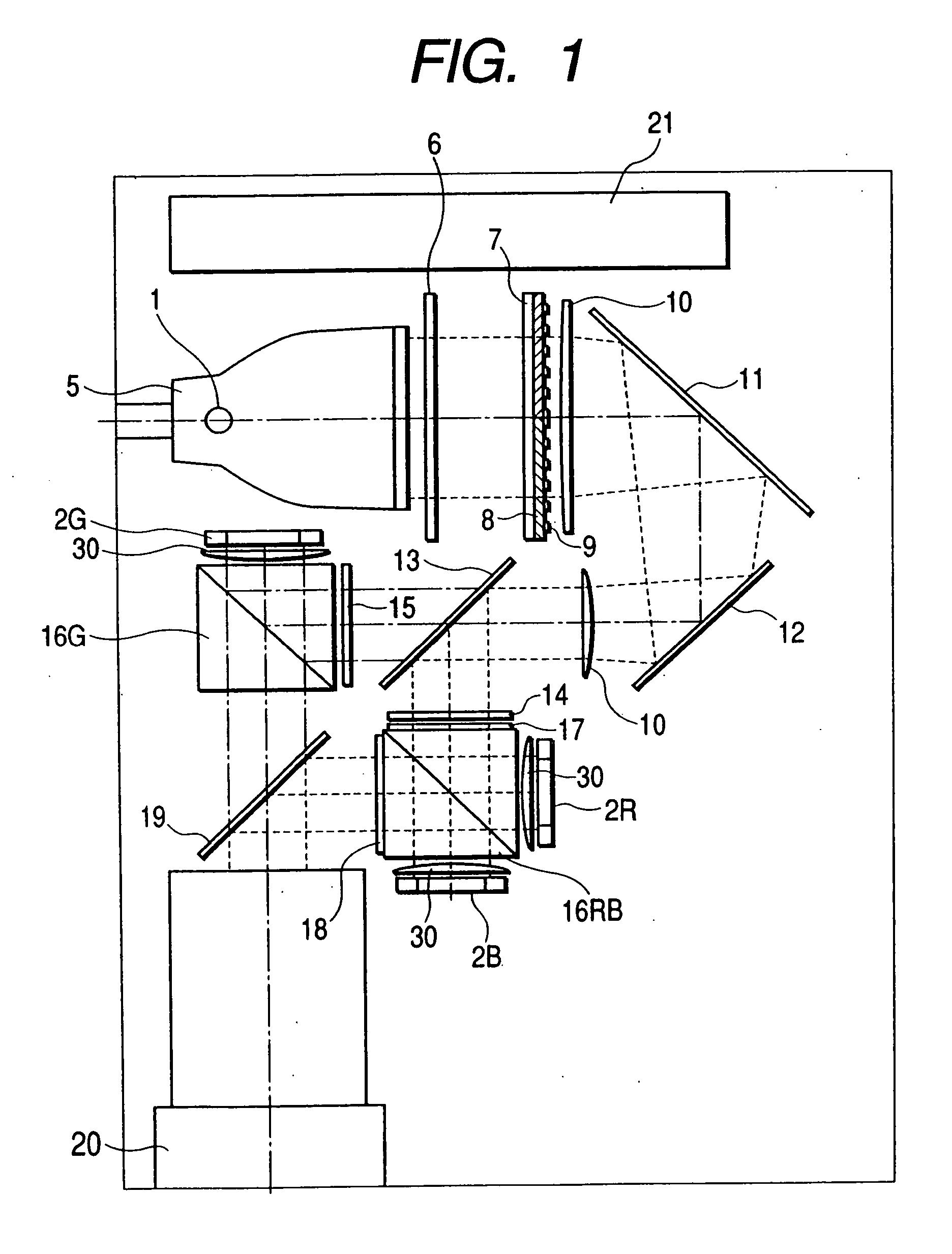
[0064]FIG. 2 is an overall plan view showing the projection type liquid crystal image display device of the invention.

[0065] The R G B color light emitted from reflective liquid crystal display elements such as the reflective liquid crystal display elements 2R, 2G, 2B, or reflective intense inductive image display elements or drive micromirror image display elements, is analyzed by the polarized beams splitter 16G and polarized beam splitter 16RB that constitute the color separating / combination elements, and the color is then recombined by the dichroic prisms 19a and the light passes through a projection means 20 such as a zoom lens and arrives on the screen. The image formed on the reflective liquid crystal display elements 2R, 2G, 2B by the projection means 20 is projected as an enlarged image on the screen. The prism 19a of this invention has a size larger than the polarized beam splitter so that the light beam is not eclipsed, and the overall structure is compact so that the siz...

third embodiment

[0066]FIG. 3 is an overall plan view showing the projection type liquid crystal image display device of the invention.

[0067] The light passes the condenser lens 30 and in order to illuminate the reflective liquid crystal display elements 2R, 2G, 2B for each R G B color, the light of a designated wavelength band is first converted to a polarization direction by means of a designated wavelength converter element 28. In this case, if the illuminating light is S polarized light then it is converted to P polarized light, and separated into each color by the wideband polarized beam splitter 16 RGB. If for instance G polarized light is converted by the designated wavelength converter element 28, the light is divided into two portions, one G light and the other R, B light by the polarized beam splitter 16 RGB and then input to the respective exclusive polarized color separator / synthesizer element consisting of polarized beam splitters 16G, 16RB. In other words, the P polarized light of the ...


PUM


Abstract

An image display device has three reflective image display elements for red, green and blue to form an optical image according to a video signal from light output from a light source, and an optical system to supply light onto the display elements and to combine and output the light reflected from the display elements. The image display device includes a first polarity converting unit to convert luminous flux from the light source to S polarized light, a first polarized beam splitter, and second polarized beam splitter. The reflective image display element for green is provided in a vicinity of the first polarized beam splitter, and the light reflected by the first polarized beam splitter and input to the reflective image display element for green is S polarized light. The light output from the reflective image display element for green permeates the first and second polarized beam splitters.

Description

CROSS REFERENCE TO RELATED APPLICATION [0001] This application is continuation of U.S. Ser. No. 10 / 638,804, filed Aug. 12, 2003, which is a continuation of application Ser. No. 09 / 810,571, filed Mar. 19, 2001, now U.S. Pat. No. 6,626,540, the subject matter of which is incorporated by reference herein.BACKGROUND OF THE INVENTION [0002] 1. Field of the Invention [0003] The present invention relates to a display device for projecting images on a screen using light valve elements such as liquid crystal panels or reflective liquid crystal elements and relates in particular for example, to an image display device for liquid crystal projector devices, reflective image display projector devices, liquid crystal televisions and projection type display devices, etc. [0004] 2. Description of the Related Art [0005] Projection type display devices such as liquid crystal projectors are known in the related art as a means to irradiate light from a light source such as an incandescent bulb onto lig...

Claims


Application Information

Patent Timeline
Patent Type & Authority Applications(United States)
IPC IPC(8): G02B27/14G03B21/14G03B33/12H04N5/74H04N9/31
CPCG02B27/1026G02B27/1073G02B27/14G02B27/145G02B27/283G03B21/10G03B21/2073G03B33/12H04N5/7441H04N9/3105H04N9/3167H04N9/3197G03B21/2066G03B21/14G03B21/006
Inventor OUCHI, SATOSHIIMAHASE, TAROMIYOSHI, TOMOHIROABE, FUKUYASU
Owner MAXELL HLDG LTD
Why Eureka
Try Eureka