Display panel, method of manufacturing the same, and display device

a display panel and manufacturing method technology, applied in non-linear optics, instruments, optics, etc., can solve the problems of small bonding strength, non-uniform brightness, and high probability of arbitrary movement of spherical pads, and achieve uniform brightness of display panels, increase bonding strength, and good evenness

Active Publication Date: 2017-05-04
BOE TECH GRP CO LTD
View PDF10 Cites 1 Cited by
  • Summary
  • Abstract
  • Description
  • Claims
  • Application Information

AI Technical Summary

Benefits of technology

[0027]In the display panel according to the embodiment of the invention and the display panel manufactured through the method according to the embodiment of the invention, the supporting posts are provided and fixed in the space between the substrates, such that the spacing between the substrates can be maintained in a long period of time, and uniformity of brightness of the display panel can be maintained in a long period of time. Provision of the adhering parts at regions corresponding to the supporting posts may increase bonding strength between the substrates. Moreover, as the adhering parts are disposed in the recesses, the surface of the substrate where the adhering parts are located may have good evenness, and the material for forming the adhering parts may be prevented from spreading out and influencing performances of its peripheral components.
[0028]Since the display device according to the embodiment of the invention utilizes the above display panel, it not only has the advantageous of the display panel, but also has a better display effect.

Problems solved by technology

However, as a plastic substrate is flexible, when the plastic substrate is bent or curled like a paper, the spherical pads are very likely to be moved to arbitrary positions, such that agglomeration of spherical pads occurs in an active region.
On one hand, it may lead to non-uniformity in brightness in a certain tone during displaying, and on the other hand, the spherical pads distributed in the space between the substrates for maintaining the spacing of the substrates will lead to a small adhering area between the substrates, resulting in a small bonding strength.

Method used


Image

  • Display panel, method of manufacturing the same, and display device
  • Display panel, method of manufacturing the same, and display device
  • Display panel, method of manufacturing the same, and display device

Examples


Embodiment Construction

[0033]Exemplary embodiments of the present disclosure will be described hereinafter in detail with reference to the attached drawings, wherein the like reference numerals refer to the like elements. The present disclosure may, however, be embodied in many different forms and should not be construed as being limited to the embodiment set forth herein; rather, these embodiments are provided so that the present disclosure will be thorough and complete, and will fully convey the concept of the disclosure to those skilled in the art.

[0034]In one aspect of the invention, there is provided a display panel.

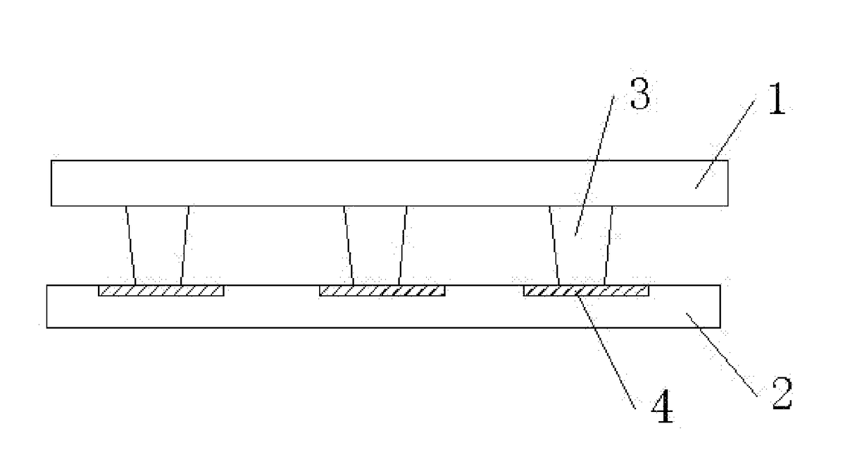
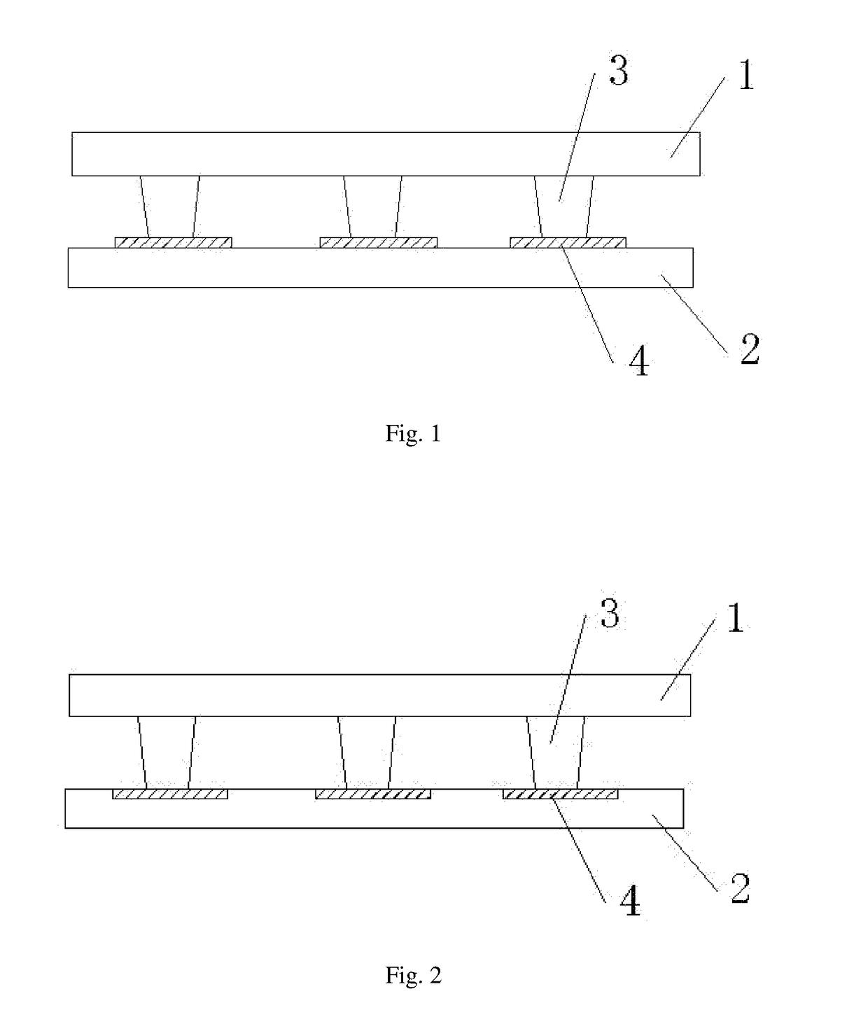
[0035]A display panel according to a first embodiment of the invention is shown in FIG. 1. The display panel includes a first substrate 1 and a second substrate 2 disposed opposite to each other. A plurality of supporting posts 3 are provided at a side of the first substrate 1 facing the second substrate, and a plurality of adhering parts 4 are provided at a side of the second substrate 2...


PUM

PropertyMeasurementUnit
temperatureaaaaaaaaaa
pressureaaaaaaaaaa
pressureaaaaaaaaaa

Abstract

A display panel, a method of manufacturing the display panel and a display device including the display panel are disclosed. The display panel includes a first substrate; a second substrate disposed opposite to the first substrate; a plurality of supporting posts disposed on a side surface of the first substrate facing the second substrate; and a plurality of adhering parts disposed on a side surface of the second substrate facing the first substrate, each of the plurality of adhering parts corresponding to the plurality of supporting posts respectively. Two opposite side surfaces of each of the plurality of adhering parts are respectively in contact with the corresponding one of the plurality of supporting posts and the second substrate to adhere the corresponding one of the plurality of supporting posts to the second substrate.

Description

CROSS-REFERENCE TO RELATED APPLICATION[0001]This application claims benefits of Chinese Patent Application No. 201510737391.X filed on Nov. 3, 2015 in the State Intellectual Property Office of China, a whole disclosure of which is incorporated herein by reference.BACKGROUND[0002]Field of the Invention[0003]Embodiments of the invention relate to the field of display technology, and specifically, to a display panel, a method of manufacturing the same, and a display device.[0004]Description of the Related Art[0005]With development of wireless mobile communication, information display devices and display panels are widely used as communication terminal devices. At the same time, to solve a problem that a glass substrate will be broken when the device falls, a material of the substrate of the terminal device having a mobile communication function has been changed from glass to plastic, such that a flexible display becomes possible.[0006]In a typical display device, characteristics such a...

Claims


Application Information

Patent Timeline
Patent Type & Authority Applications(United States)
IPC IPC(8): G02F1/1339
CPCG02F2202/28G02F1/13394G02F1/13398
Inventor HUANG, HUA
Owner BOE TECH GRP CO LTD
Why Eureka
Try Eureka