3D bullet and cartridge case analysis

a 3d-printed, case-based technology, applied in the field of 3d-printed bullet and cartridge case analysis, can solve the problems of affecting the performance of the technique, lack of robustness of the technique, and many drawbacks of the 2d-printed ballistic matching techniqu

Active Publication Date: 2005-11-03
ULTRA ELECTRONICS FORENSIC TECH INC
View PDF3 Cites 9 Cited by
  • Summary
  • Abstract
  • Description
  • Claims
  • Application Information

AI Technical Summary

Benefits of technology

[0013] In another preferred embodiment, the present invention provides an apparatus for mapping a surface of a BPOE. The apparatus comprises a holder for holding the BPOE and a measurement unit for measuring a light intensity from the BPOE as a function of a measurement position, wherein

Problems solved by technology

However, ballistic matching techniques based on 2D-imaging present many drawbacks.
In particular, it is found that the technique lack robustness: the images resulting from a 2D imaging are very dependent on the exact way the BPOE is illuminated and

Method used


Image

  • 3D bullet and cartridge case analysis
  • 3D bullet and cartridge case analysis
  • 3D bullet and cartridge case analysis

Examples


first embodiment

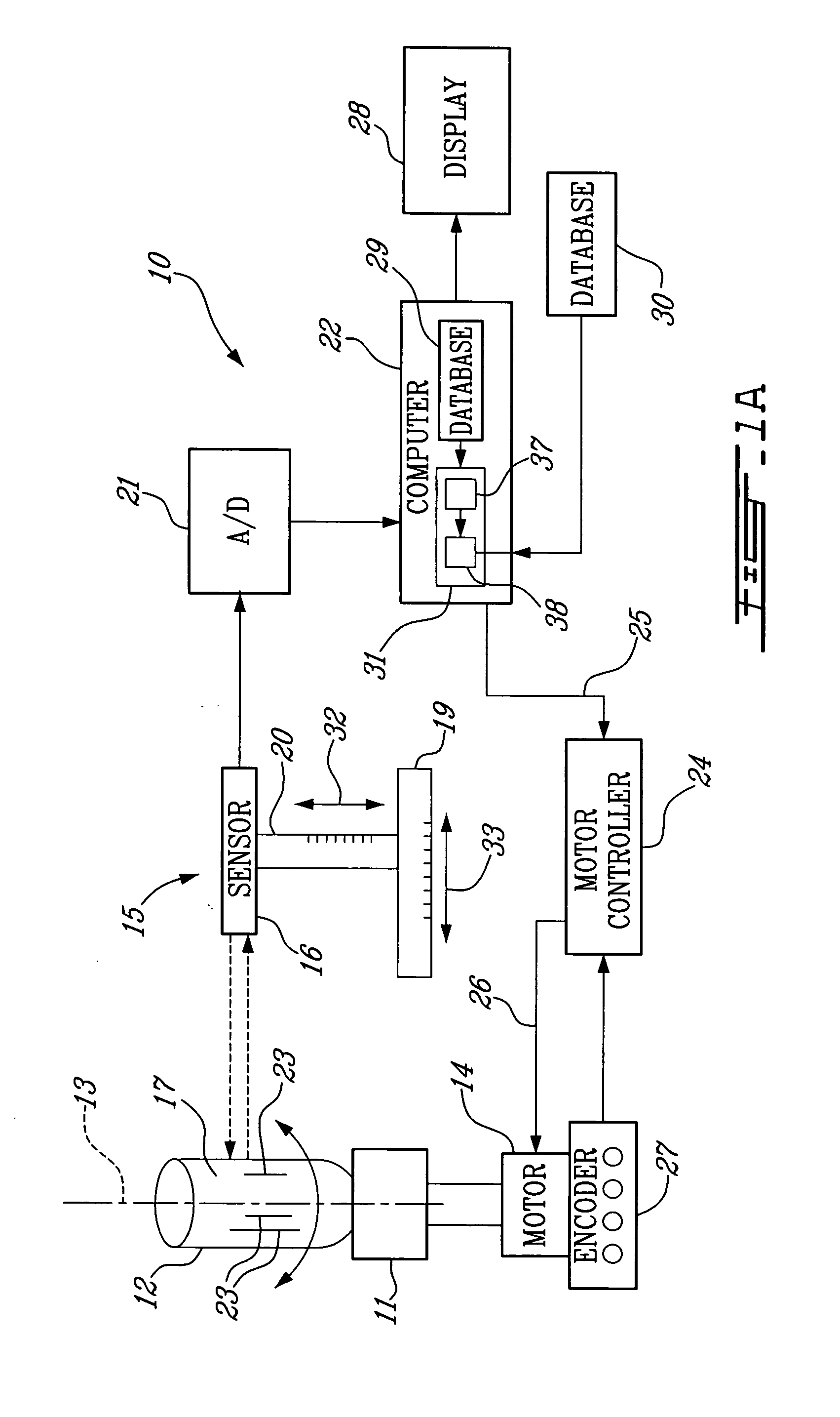
[0030] System for mapping a bullet surface: In the present invention, a computerized system 10 equipped with a confocal microscope is used to obtain a surface mapping of a bullet. This embodiment is illustrated in FIG. 1A and can be described as follow. The system 10 comprises as the main elements a bullet holder 11 to hold a bullet 12, a confocal microscope sensor 16 to acquire a relief map of a surface 17 of the bullet 12, and a displacement system controlled by a computer 22, to vary the relative position between the bullet 12 and the sensor 16. It is worth mentioning that although, in certain embodiments of the present invention, a confocal microscope is used as the mapping sensor, other sensors could also be used (Moiré, Laser Confocal Scanning Microscopy, Pixel Contrast).

[0031] In this first embodiment, the bullet holder can rotate the bullet 12 about the rotation axis 13 shown in FIG. 1A, via a motor 14. Using sensor 16, this rotation movement of the bullet 12 permits the mea...
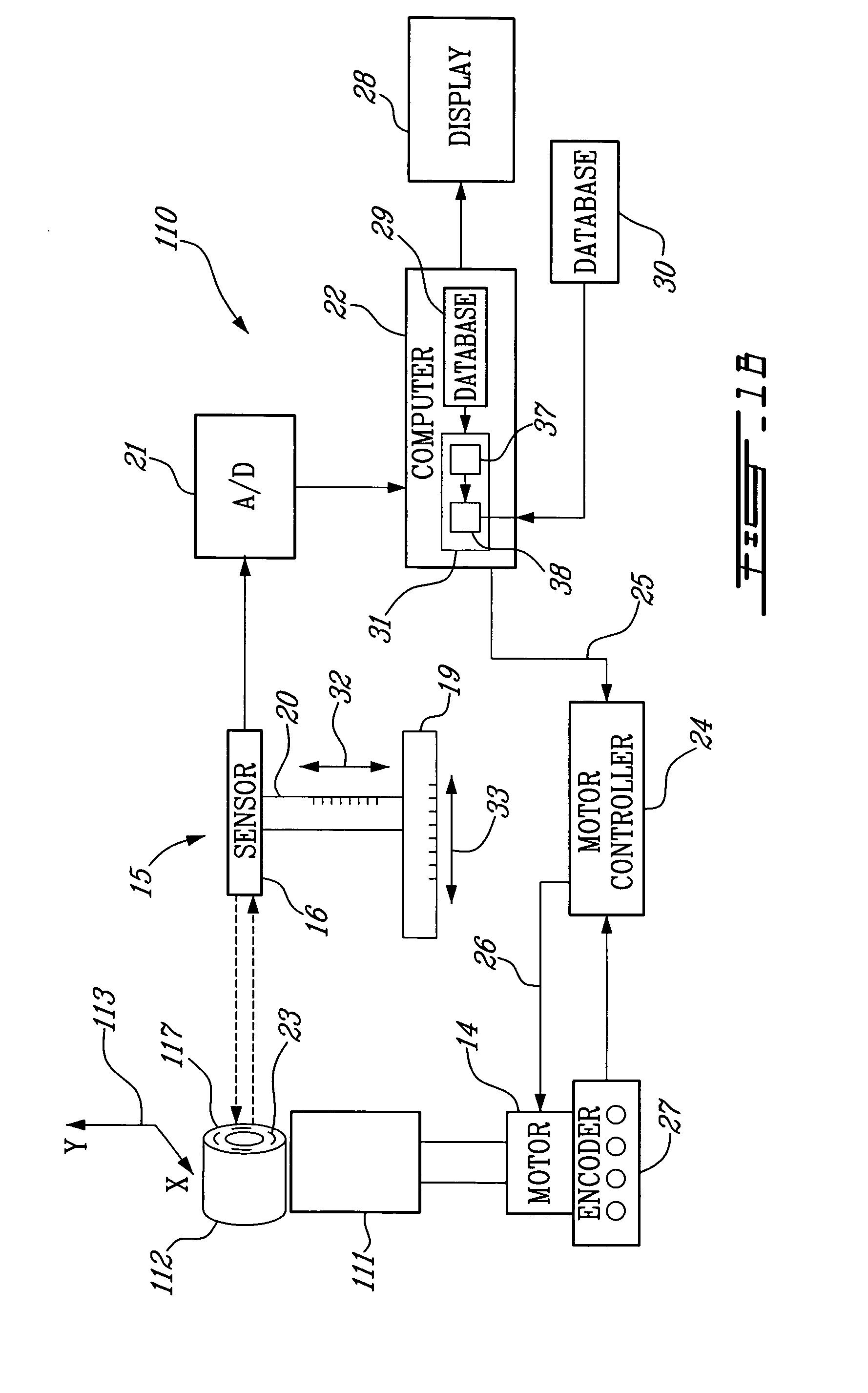
second embodiment

[0037] In this second embodiment, the rest of the system 110 is the same as for the system 10, and therefore will not be further described.

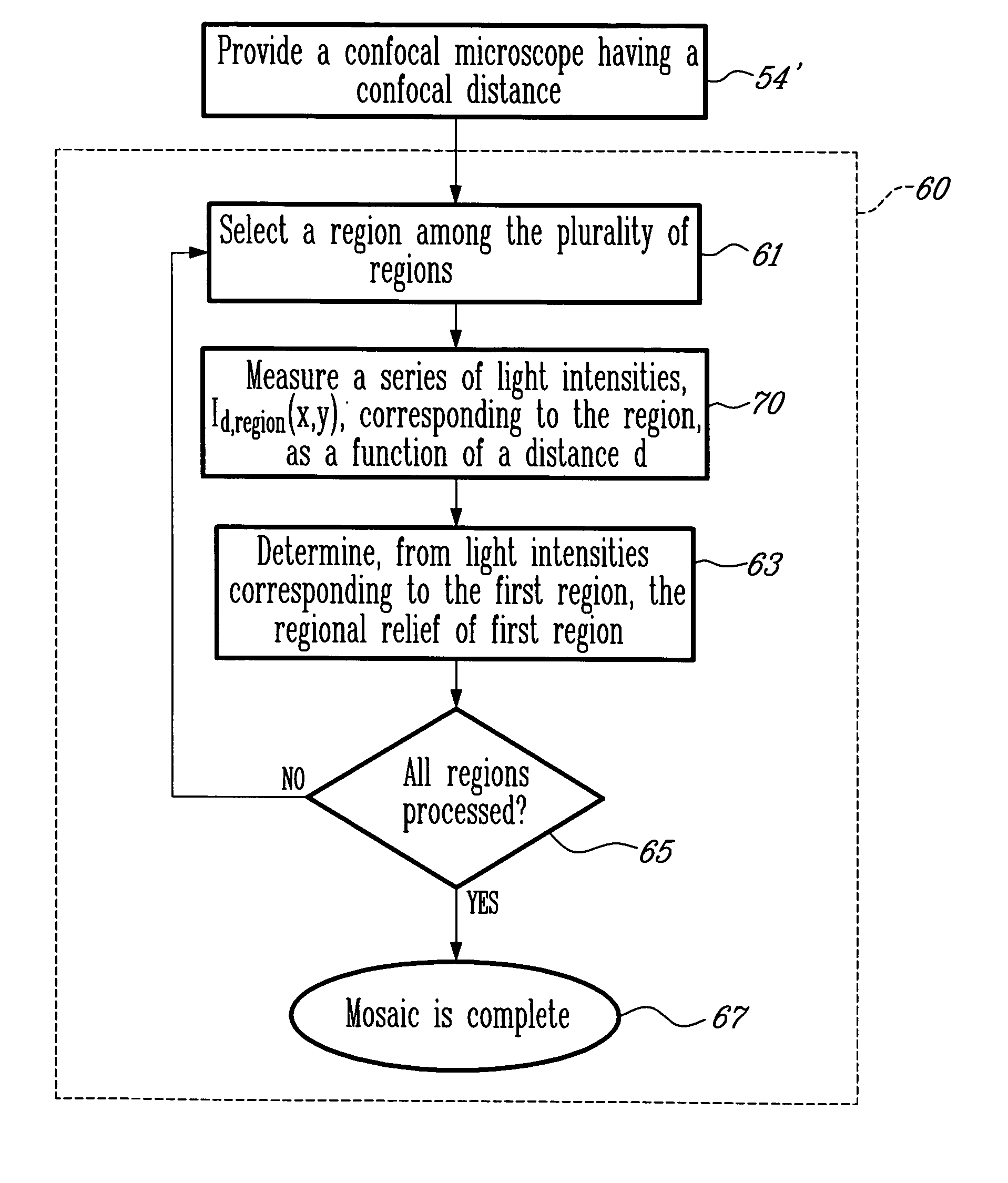
[0038] A surface mapping method: We will now describe in detail a method 50 of mapping a surface of a BPOE 9. The method applies equally well to a bullet 12 or to a cartridge case 112.

[0039] The main steps of a surface mapping method 50 of a BPOE according to an embodiment of the present invention are listed in FIG. 2A and are described in more detail in the following paragraphs.

[0040] A BPOE 9 under examination is provided at step 52 and a measurement unit adapted to acquire a relief map of a surface of the BPOE is provided at step 54. Then, at step 56, the measurement unit acquires the relief map to thereby map the surface of the BPOE 9. In one embodiment, this surface is a peripheral band of a bullet 12 corresponding to a surface region of the bullet 12 expected to contain significant striations 23 produced when the firearm is fired. In anot...


PUM


Abstract

A method and an apparatus to obtain a surface mapping of a ballistic piece of evidence (BPOE) under examination, such as a bullet or a spent cartridge case, that can be used thereafter as a 3D signature for identifying purpose during ballistic test comparison. The method comprises providing a measurement unit adapted to acquire a relief map of the surface of the BPOE and acquiring with the measurement unit the relief map of the surface to thereby obtain the mapping of the surface of the BPOE. Preferably, the measurement unit of the present invention comprises a confocal sensor such as confocal microscope. Also, the present invention includes acquiring the relief map of the bullet surface or of the cartridge case surface by acquiring and assembling a mosaic of regional reliefs that are partly overlapping with their surroundings regional reliefs.

Description

CROSS-REFERENCE TO RELATED APPLICATIONS [0001] This application is a continuation-in-part of U.S. Ser. No. 10 / 836,315 filed May 3, 2004.FIELD OF THE INVENTION [0002] The invention relates to a system and a method for the analysis and comparison of ballistic pieces of evidence such as fired bullets and spent cartridge cases. More specially, it relates to a computerized system and method for ballistic piece of evidence (BPOE) analysis based on a 3D imaging of the BPOE surface. BACKGROUND OF THE INVENTION [0003] In the field of forensic science, investigations of crimes involving firearms use ballistic comparison test to determine if a bullet or a spent cartridge case found on the crime scene has been fired by a firearm in question. Ballistic comparison tests rely on the fact that when a bullet is fired by a firearm, striations are created on the bullet surface and these striations have enough unique features to represent a signature of the firearm. With regards to spent cartridge case...

Claims


Application Information

Patent Timeline
IPC IPC(8): F42B35/00G06K9/00G06T5/00G06T5/50G06T7/00
CPCF42B35/00G01B11/306G06K9/00201G06K2009/2045G06T2200/04G06T5/006G06T5/50G06T7/0024G06T3/4038G06T7/30G06V20/64G06V10/16G06V20/66
Inventor NADEAU, ERICPAGES, MYRIAMROBERGE, DANNYROY, ALAINLEGER, MARTIN
Owner ULTRA ELECTRONICS FORENSIC TECH INC
Why Eureka
Try Eureka