Mouthpiece for use in a spirometer

a spirometer and mouthpiece technology, applied in the field of measuring air pressure, can solve the problems of only limited degree of air flow obstruction, variable resistive elements, and difficulty in comparing breath tests performed on the two different mouthpieces, and achieve the effects of small resistance, large resistance to his breathing, and convenient us

Inactive Publication Date: 2005-11-03
MEDDORNA
View PDF16 Cites 16 Cited by
  • Summary
  • Abstract
  • Description
  • Claims
  • Application Information

AI Technical Summary

Benefits of technology

[0013] In one embodiment of the invention, the mouthpiece comprises a tube forming a conduit between an upstream end and a substantially closed downstream end. An opening is formed through the tube and is proximate to the downstream end of the tube. The mouthpiece also comprises a resistive element that is positioned substantially across the tube opening. In addition, the mouthpiece may comprise an outer sleeve that is slid along the exterior of the tube. The outer sleeve may be slid along the tube thereby covering portions of the tube opening in varying amounts. Thus, the outer sleeve may be slid into one position wherein the tube opening is uncovered and a small amount of resistance is encountered by the patient. The outer sleeve may then be advanced into a closed position wherein the tube opening is substantially sealed and the patient experiences a large resistance to his breathing. Many partially closed positions may also exist between the open and closed positions thereby allowing for

Problems solved by technology

Without calibrating these “imperfect” resistive elements, a physician would have difficulty comparing a patient's breath tests performed on the two different mouthpieces.
These variable resistive elements provide, however, only limited degrees of air flow obstruction such as relatively unimpeded flow (i.e., “open configuration”), whereby the plug is not positioned within or across an opening in the mouthpiece, and absolutely no flow (i.e., “closed configuration”) whereby the plug is positioned across an opening precluding substantially any air flow.
These resistive elements do not provide a “partially open” configuration, thereby allowing limited air flow, that can be maintained in a static position long enough to obtain physiological measurements.
Other examples of prior art resistive elements may provide a partially open configuration that allows varied amounts of resistance to air f

Method used


Image

  • Mouthpiece for use in a spirometer
  • Mouthpiece for use in a spirometer
  • Mouthpiece for use in a spirometer

Examples


Embodiment Construction

Slidable Outer Sleeve

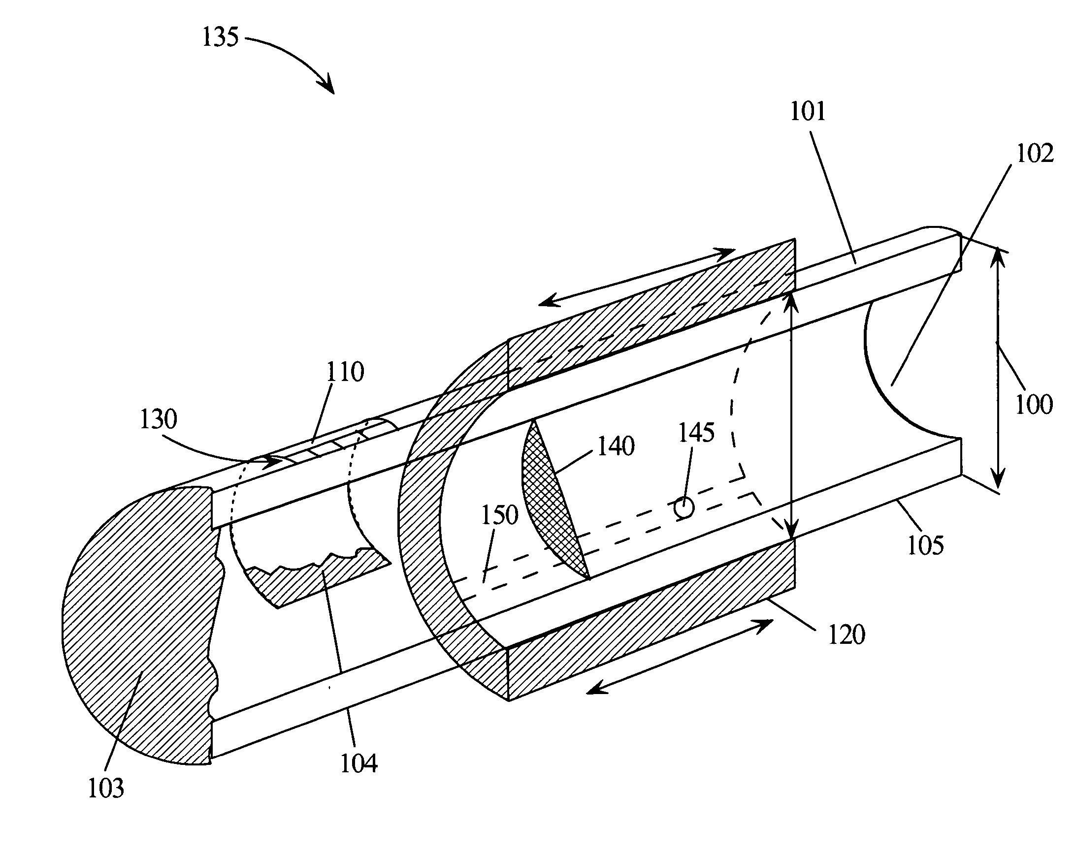
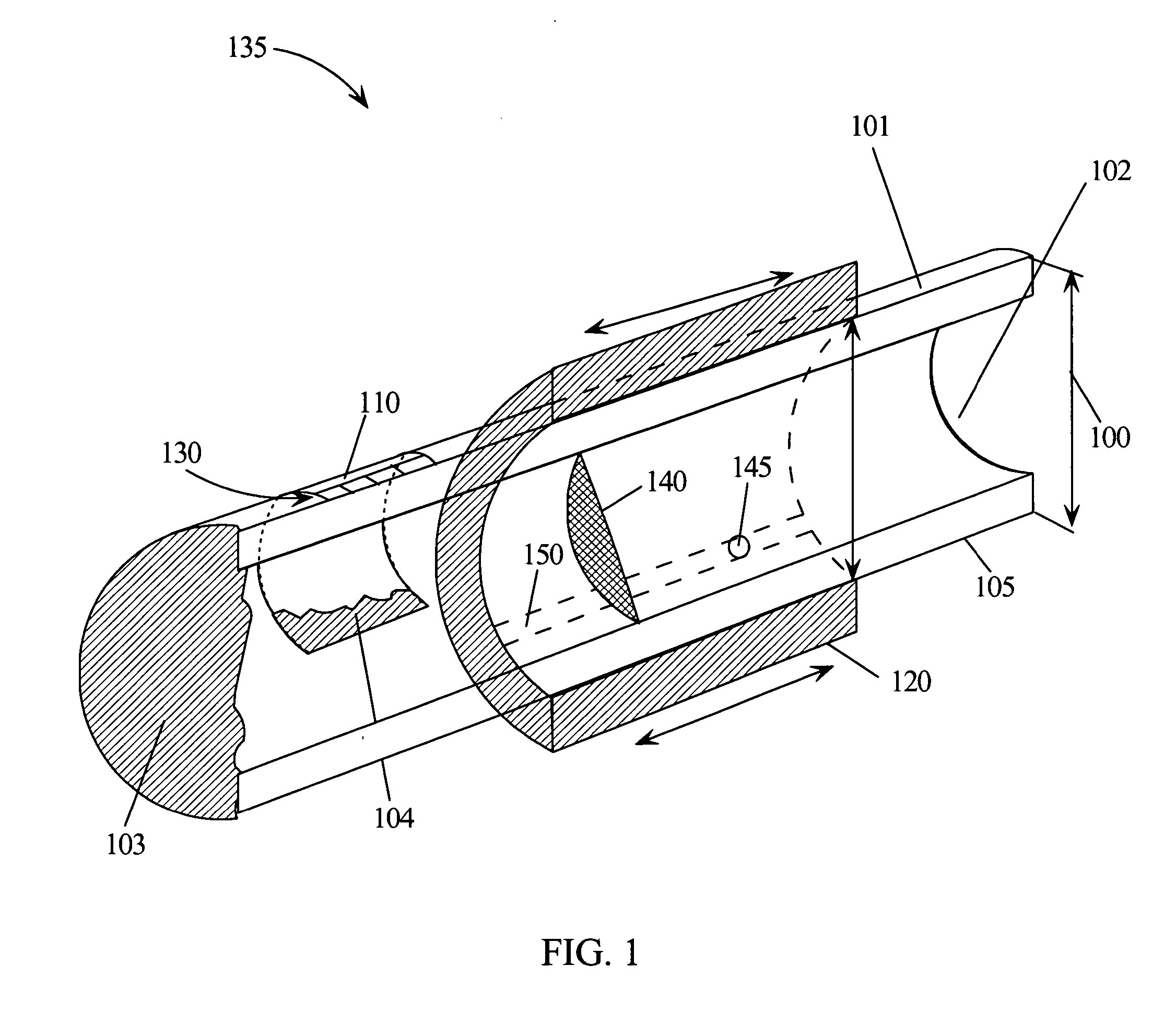
[0029] As illustrated in FIG. 1, one example embodiment of the invention generally entails a spirometric mouthpiece or breathing tube 135 comprising a first tube 101 with an upstream or distal end 102 that a patient may blow into. The tube 101 also has a downstream or proximal end 103. The tube 101 may have one or more openings 110 formed within or through the tube wall 105. The opening 110 may be located near the upstream end 102 or downstream end 103 or anywhere in-between. In addition, the downstream end 103 may be open or closed.

[0030] The one or more openings may be covered with porous fabric 104 to provide resistance to air flow thereby constituting a resistive element. When the patient blows into the mouthpiece, the porous fabric 104 resistive element cooperates with the tube 101 to provide a conduit for the patients' air while providing resistance to the air flow so that the air pressure can be generated and recorded.

[0031] The mouthpiece may also in...


PUM


Abstract

The invention entails a mouthpiece for use in a spirometer. In one embodiment of the invention, the mouthpiece comprises a tube forming a conduit between an upstream end and a substantially closed downstream end. An opening is formed through the tube and is proximate to the downstream end of the tube. The mouthpiece also comprises a resistive element that is positioned substantially across the tube opening. In addition, the mouthpiece comprises an outer sleeve that is slide along the exterior of the tube. The outer sleeve may be slid along the tube thereby covering portions of the tube opening in varying amounts. Thus, the outer sleeve may be slid into one position wherein the tube opening is uncovered. The outer sleeve may then be advanced into a closed position wherein the tube opening is substantially sealed. Many partially closed positions exist between the open and closed positions thereby allowing for variable amounts of resistance to air flow. To clearly indicate to the user how far the outer sleeve has been advanced, markings may be made on the outer sleeve or tube indicating, for example, the first tube opening is fifty percent occluded.

Description

BACKGROUND OF THE INVENTION [0001] 1. Field of the Invention [0002] The present invention relates to the field of measuring air pressure, and related characteristics, associated with air discharged from a patient's lungs during physiological testing, including spirometric and heart rate variability studies. More specifically, the invention is related to an apparatus that the patient may breath into during such studies whereby the apparatus provides resistance to air flow and allows for pressure readings to be taken. [0003] 2. Description of the Related Art [0004] Spirometry concerns methods for studying pulmonary ventilation. In a typical spirometry study, a patient blows into a spirometer which includes a mouthpiece with a known resistance. The spirometer allows a physician to measure the patient's respiratory air pressure, flow rate and volume. A physician can then use those results to obtain respiratory-related physiological values such as tidal volume, inspiratory reserve volume...

Claims


Application Information

Patent Timeline
IPC IPC(8): A61B5/08A61B5/097
CPCA61B5/097A61B5/4035
Inventor POUGATCHEV, VADIM I.ZHIRNOV, YEVGENIY N.GRIBKOV, EVGUENI N.FERRIS, MARK
Owner MEDDORNA
Why Eureka
Try Eureka