Fluid transportation system and method of setting fluid ejection amount

a technology of fluid transportation system and fluid ejection amount, which is applied in the direction of computer-aided medicine prescription/delivery, drug and medication, etc., can solve the problems of variable flexibility of the diameter of the tube, unchangeable condition once determined, and difficulty in setting the fluid ejection amount, etc., to achieve accurate ejection amount of fluid and accurate setting and controlling a small amoun

Inactive Publication Date: 2009-12-17
SEIKO EPSON CORP
View PDF18 Cites 13 Cited by
  • Summary
  • Abstract
  • Description
  • Claims
  • Application Information

AI Technical Summary

Benefits of technology

[0013]In view of the above problems, an advantage of some aspects of the present invention is to provide a fluid transportation system equipped with a communication device and capable of accurately setting and controlling a small amount of ejection of the fluid among a fluid transportation device and an ejection data processing device and a method of setting an accurate ejection amount of a fluid.

Problems solved by technology

However, the ejection condition once determined is unchangeable, and there arises a problem that it is difficult to set the fluid ejection amount while arbitrarily changing the form of usage or the condition of administering the medicinal liquid.
Further, there might be caused a variation in diameter of the tube having flexibility in the manufacturing process thereof.
Such a variation in diameter of the tube causes a variation in ejection amount of the liquid, and in particular in the case of the application to administration of a medicinal liquid, the variation in tube diameter is a substantive issue because a small amount of ejection is continuously performed and accurate ejection amount control is required.
However, in the first and second related art described above, there is a problem that the accurate adjustment of the ejection amount in consideration of the variation in tube diameter can hardly be performed.
Further, it is conceivable that it does not cope with a variation in remaining power or voltage of a battery as a power supply, improper driving of the pump, shortage of drive period, and so on, and consequently, it is inferred that a significant problem unable to be left unsolved arises in the case of administration of a medicinal liquid.
Further, by detaching the fluid transportation device from the communication device, the connection between the fluid transportation device and the communication device is broken.
However, it is known that in the diameter of the tube, there is caused a variation in the manufacturing process, and in particular the difference among the production lots is often caused.
When the battery voltage is lowered, normal driving of the stepping motor might become difficult, and the predetermined ejection amount might hardly be obtained.
Therefore, the user of the fluid transportation system is not allowed to modify the fundamental data, and further, the provider of the fluid transportation system is not allowed to modify the ejection data.

Method used


Image

  • Fluid transportation system and method of setting fluid ejection amount
  • Fluid transportation system and method of setting fluid ejection amount
  • Fluid transportation system and method of setting fluid ejection amount

Examples


first embodiment

[0092]Firstly, the invention will be described.

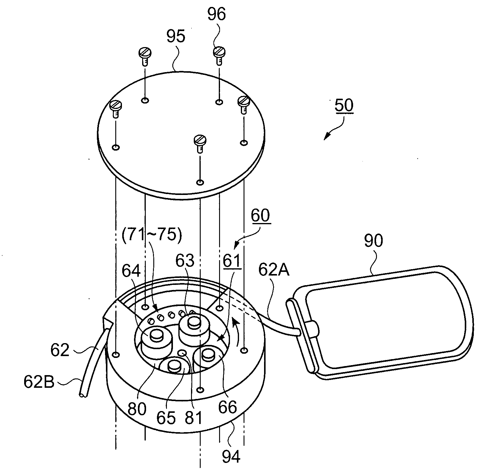
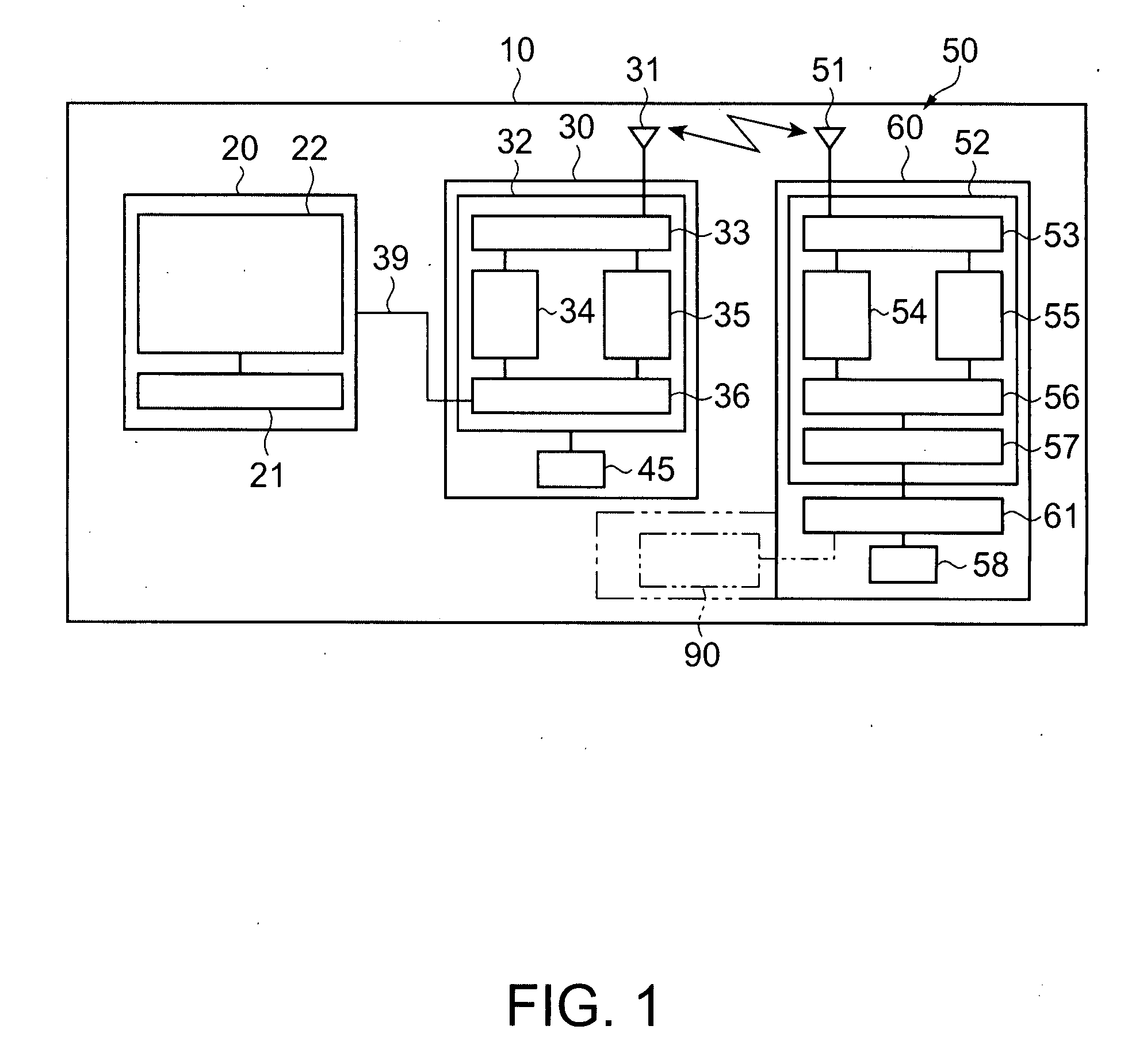
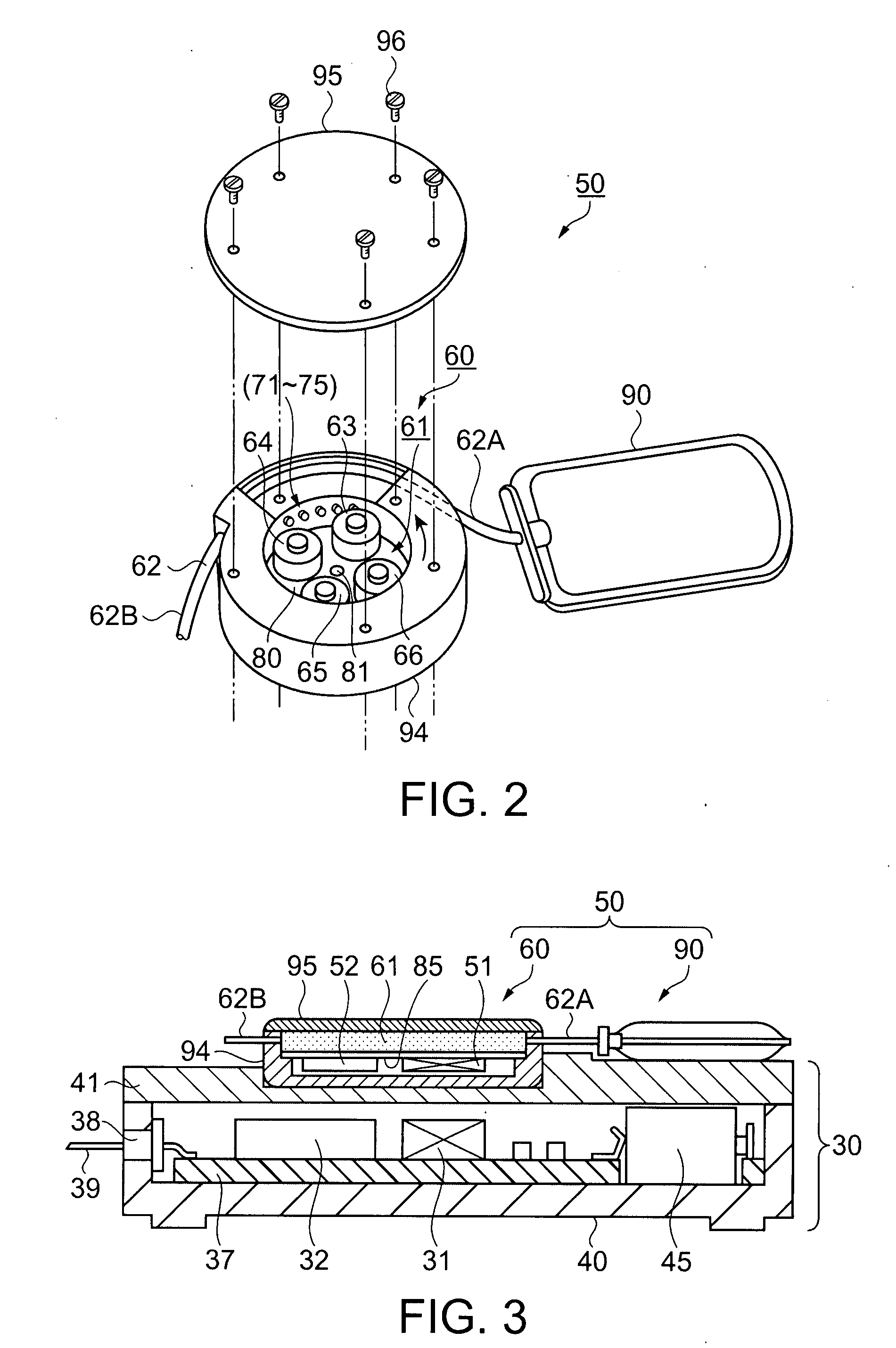
[0093]FIGS. 1 through 3 show a fluid transportation system and a fluid transportation device according to the first embodiment of the invention.

[0094]FIG. 1 is a block diagram showing a configuration of the fluid transportation system 10 according to the present embodiment. In FIG. 1, as a fundamental configuration, the fluid transportation system 10 of the present embodiment is composed of a personal computer (PC) 20 as an ejection data processing device, a communication device 30, and a fluid transportation device 50.

[0095]The PC 20 includes an operation section 21 as an input device for inputting driving condition data of the fluid transportation device 50, a display section 22 for displaying the driving condition data thus input, and in addition, functions provided to a general PC such as an calculation function, storage function, and so on. The driving condition data input to the PC 20 is transmitted to the communication device 30 ...

second embodiment

[0138]FIG. 4 is a block diagram showing the configuration of the fluid transportation system 100 according to the In FIG. 4, the fluid transportation system 100 is composed of the PC 20 as the ejection data processing device, a communication device 130, and a fluid transportation device 150.

[0139]The communication device 130 is composed of a communication control circuit 132, and the battery 45 as the power supply, and the communication control circuit 132 is composed of the memory circuit 36, a light reception control circuit 134, a light emission control circuit 135, a light receiving element 133, and a light emitting element 131. The driving condition data is input to the fluid transportation device 150 by means of an optical signal emitted from the light emitting element 131.

[0140]The fluid transportation device 150 is composed of a micro pump 160 including a fluid transportation device control circuit 152 and the pump unit 61, the battery 58 as the power supply, and the fluid ...

third embodiment

[0157]FIG. 6 is a block diagram showing the configuration of a fluid transportation system 200 according to the In FIG. 6, the fluid transportation system 200 is composed of the PC 20 as the ejection data processing device, a communication device 230, and a fluid transportation device 250.

[0158]The communication device 230 is composed of a communication control circuit 232 including the memory circuit 36 and transmission reception control circuit 234, and the battery 45 as the power supply. Further, connection terminals 97, 98 as second connection terminals are connected to the transmission reception control circuit 234. The communication is established by the connection terminals 97, 98 having contact with connection terminals 197, 198 as first connection terminals provided to a micro pump module 260.

[0159]The fluid transportation device 250 is composed of the micro pump module 260 including the pump unit 61 and a fluid transportation device control circuit 252, the battery 58 as ...


PUM


Abstract

A fluid transportation system includes a fluid transportation device housing a flexible tube, a pump unit for ejecting a fluid by squeezing the tube, a communication section, and a battery, an ejection data processing device having an input device for inputting to the fluid transportation device a driving condition for ejecting a desired ejection amount of the fluid, a display section for displaying at least the driving condition, and a communication device for connecting the fluid transportation device and the ejection data processing device to each other, wherein the fluid transportation device is driven based on the driving condition input from the ejection data processing device.

Description

BACKGROUND[0001]1. Technical Field[0002]The present invention relates to a fluid transportation system and a method of setting a fluid ejection amount in the fluid transportation system. For details, the present invention relates to a fluid transportation system equipped with a miniature fluid transportation device, an ejection data processing device, and a communication device, and to a fluid ejection amount setting method for accurately setting an amount of fluid ejection.[0003]2. Related Art[0004]In recent years, application of a miniature pump, which is used for continuously administering a small amount of medicinal liquid to a patient in a form of a slow current, to treatment has been studied.[0005]For example, as first related art, there is cited a miniature peristaltic pump device suitable for attachment to a human body for slowly and continuously injecting it with an aqueous medicinal liquid in which a rotor of the pump is attached to a shaft, the rotor being provided with a...

Claims


Application Information

Patent Timeline
Patent Type & Authority Applications(United States)
IPC IPC(8): A61M5/142G16H20/17
CPCA61M5/14232A61M2005/14208G06F19/3468A61M2205/3592A61M2205/0244G16H20/17
Inventor MIYAZAKI, HAJIMEKAWASUMI, KAZUO
Owner SEIKO EPSON CORP
Why Eureka
Try Eureka