Surgical saw blade

a surgical and saw blade technology, applied in the field of surgical saw blades, can solve the problems of unwelcome increase in the vibration of the handpiece, interference with cutting, and difficulty for surgeons to perform resection without additional trauma to the patien

Inactive Publication Date: 2005-11-03
STRYKER CORP
View PDF14 Cites 79 Cited by
  • Summary
  • Abstract
  • Description
  • Claims
  • Application Information

AI Technical Summary

Problems solved by technology

Such blades, particularly in relatively forceful use by a surgeon, may experience unwanted flexing in the area of the aforementioned right angle bends, allowing the legs to shift relative to each other and thus allow their toothed ends to shift with respect to each other and out of their intended mutual position of use, thereby interfering with cutting.
Lengthening of the legs increases the mass of the blade, particularly at and near its distal end, such that, during oscillation, the increased momentum of the swinging distal portion of the blade may result in an unwelcome increase in vibration of the handpiece in the hands of the surgeon, and indeed make it more difficult for the surgeon to perform a resection without additional trauma to the patient.
The faster operating speeds (higher oscillation frequency) can present problems for prior blades.
In prior blades, the severity of the vibration may be such that the out of plane movement of the distal end of the blade is quite visible to the naked eye and in some cases the vibration may be so severe as to lead to blade breakage.

Method used


Image

  • Surgical saw blade
  • Surgical saw blade
  • Surgical saw blade

Examples


Embodiment Construction

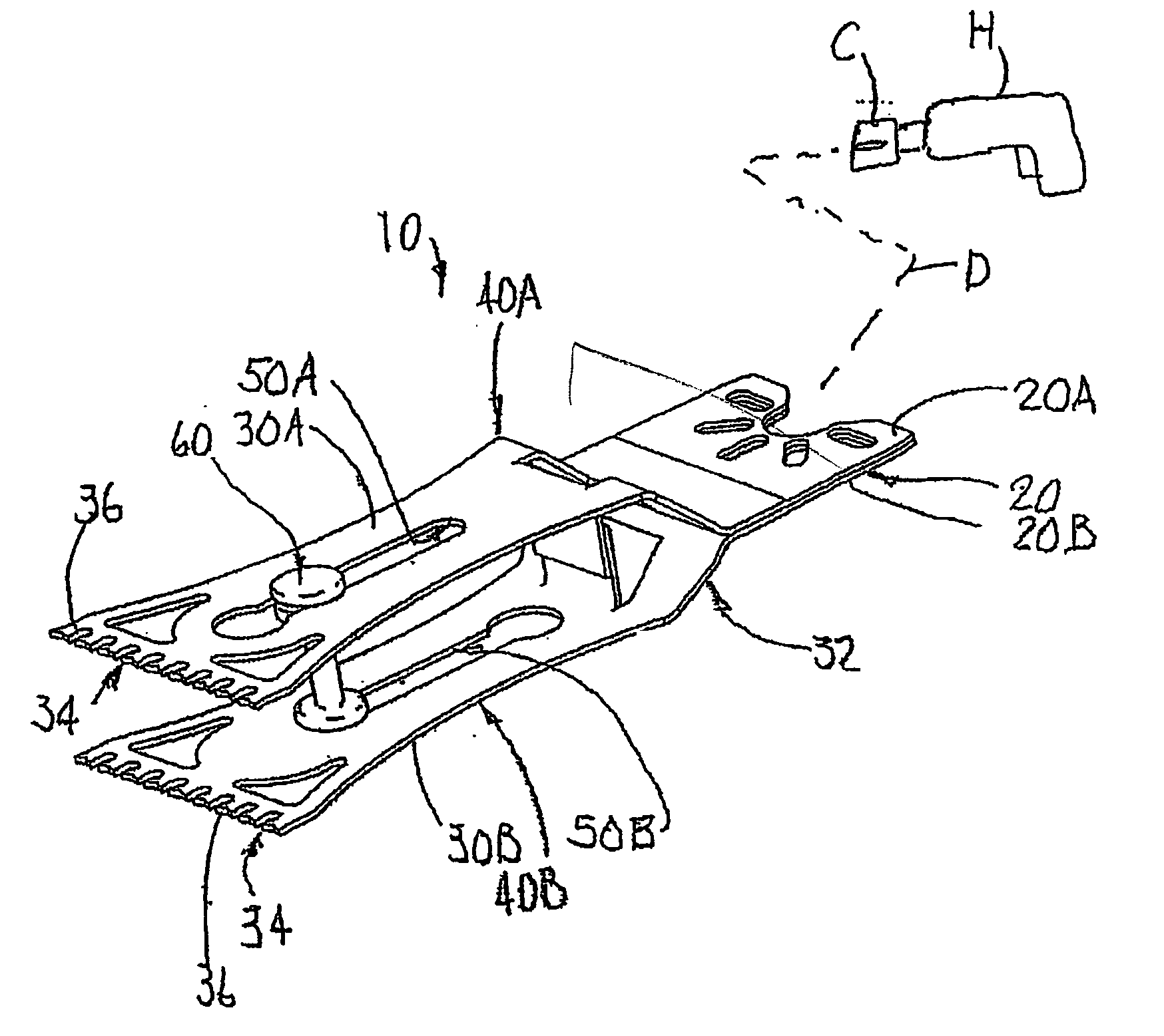
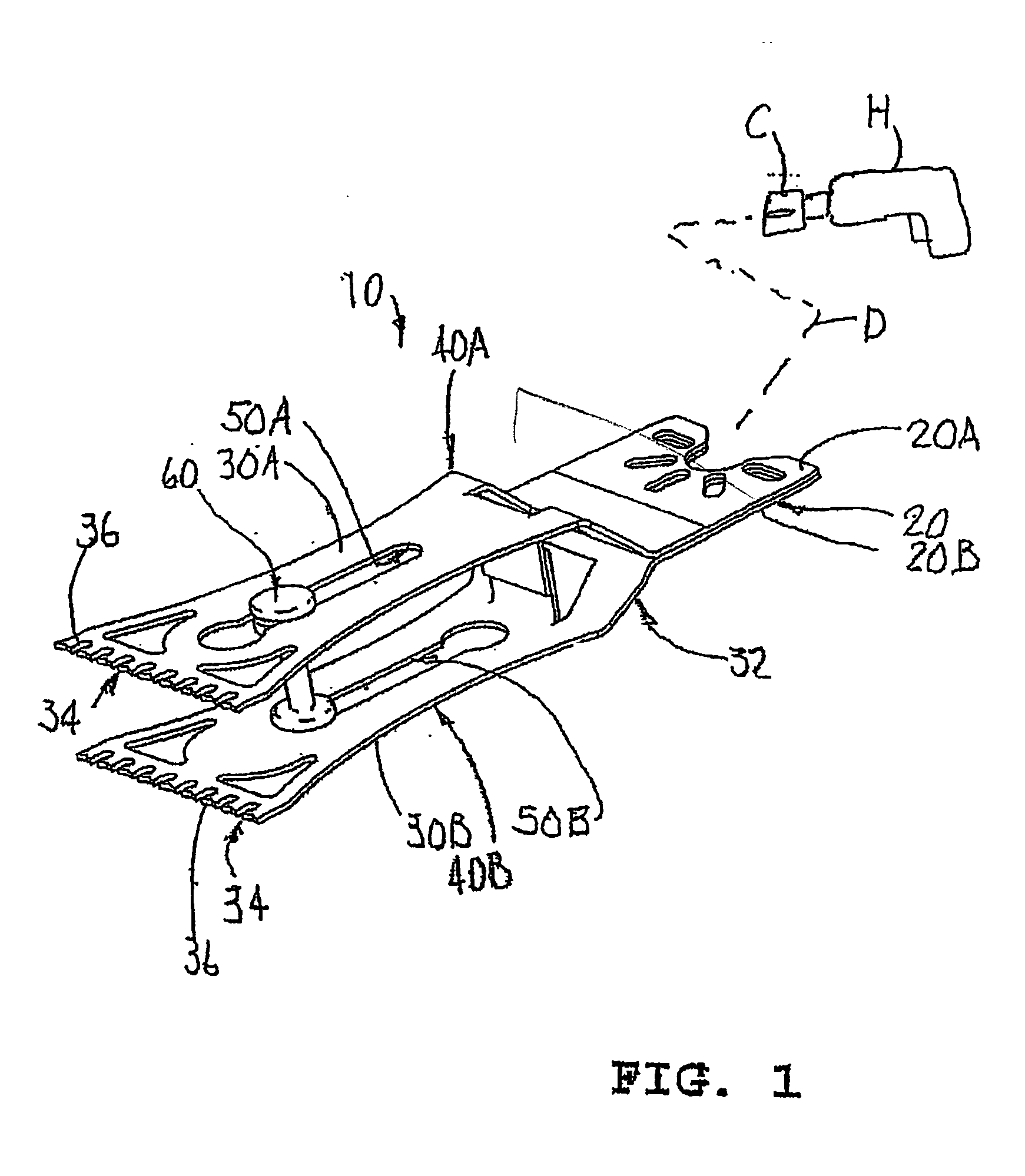
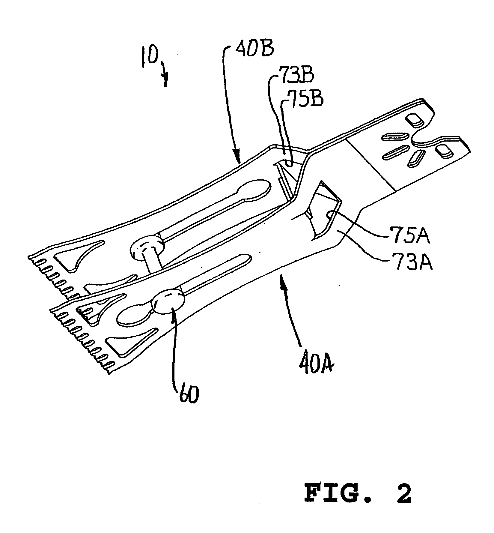
[0037] A preferred embodiment of the invention comprises a surgical saw blade 10 (FIGS. 1 and 2) of Casper type, namely of the type having a pair of parallel toothed edges spaced apart at the distal end thereof for removing a slice S (FIG. 10) of hard tissue, such as bone B.

[0038] The blade 10 is preferably constructed of flat, substantially rigid stock, typically of surgical grade, rigid, stainless steel sheet. The blade 10 (FIG. 1) has a proximal portion defining a base 20 configured, as desired, for reception and driving by the chuck C of a suitable, powered, surgical handpiece H, as schematically indicated by the dotted line D. The chuck C and the corresponding configuration of the base 20 here shown of conventional type. The blade base 20 is here configured in the manner shown in U.S. Design Patent 343 247, issued Jan. 11, 1994 and assigned to Stryker Corporation, the Assignee of the present invention. Correspondingly, chuck C and handpiece H in the present example may be of t...


PUM


Abstract

A two legged surgical saw blade comprises a base engagable with a chuck on a tool, a rigidified intermediate portion, and a lightened distal portion comprising spaced toothed legs and a spacer of reduced mass.

Description

[0001] This application claims the benefit of U.S. Provisional Application No. 60 / 566 553, filed Apr. 29, 2004.FIELD OF THE INVENTION [0002] This invention relates to a surgical saw blade, and particularly one of the types having a pair of parallel toothed edges spaced apart at its distal end. BACKGROUND OF THE INVENTION [0003] In one prior blade of the aforementioned kind, two plates are fixed together at their proximal end portions to form the blade base, which is configured to be received in a suitable chuck on a powered handpiece. In an intermediate part of the saw blade, the toothed plates are bent away from each other at right angles and after a short distance laterally are bent again at right angles to form planar legs extending distally in respective parallel planes spaced symmetrically on opposite sides of and parallel to the blade base. The distal ends of the plates are toothed. The two legs have similar, but oppositely directed, elongate keyhole shaped slots therethrough ...

Claims


Application Information

Patent Timeline
Patent Type & Authority Applications(United States)
IPC IPC(8): A61B17/14A61B17/32
CPCA61B17/14A61B17/148A61B17/141A61B17/142
Inventor CASEY, CONOR P.BRYAN, GORDONTALLON, DAVID
Owner STRYKER CORP
Why Eureka
Try Eureka