
Pallet container

Active Publication Date: 2005-11-10
MAUSER WERKE GMBH
View PDF3 Cites 2 Cited by
  • Summary
  • Abstract
  • Description
  • Claims
  • Application Information

AI Technical Summary

Benefits of technology

[0016] The present invention resolves prior art problems by providing at least the vertical tubular rods with a high tubular profile height at the intersections to therefore form limited areas of high rigidity and torsional stiffness, while the lattice rods situated outside an intersection have a low tubular profile height to form areas of lower rigidity and torsional stiffness.
[0018] According to another feature of the present invention, the areas of low tubular profile height may extend in midsection between two intersections, and the areas of high tubular profile height may be constructed in midsection across each intersection. Thus, the area of the welded intersections is effectively protected against fatigue cracks and rod fracture, i.e. not by a local desired fracture point directly next to the welding spots with rigid zones between the intersections but by the entire area between the welded intersections which is configured as more elastic, flexible zone.
[0021] Furthermore, the tubular lattice rod according to the invention is constructed torsionally softer in the long areas with smaller tubular profile height outside the intersections, i.e. it allows more twist or generates less pressure stress and tension stress on the welded intersection at same twist angle.

Problems solved by technology

During transport of filled pallet containers—in particular with contents of high specific weight (e.g. above 1.6 g / cm3)—on poor roads with trucks with firm suspension, during transport on railway or ships, the lattice rod frame is exposed to significant stress as a result of surge forces of the goods.
These dynamic transport loads generate significant continuously changing bending stress and torsion stress in the lattice tube frame, ultimately leading to fatigue cracks and resultant rod facture when exposed over respectively long periods.
As a consequence of oscillating surge pressure of the liquid content that is caused by fluctuating bending stress during transport, known lattice tube frames fracture in a relatively very short period in the tension zone of the tubular lattice rods.
Those lattice tube frames with welded round rods, e.g. disclosed in European Pat. Appl. No. EP 0 734 967 B1, and with significantly reduced tube cross sectional height in the area of the intersections (no continuous tubular profile, dents or reduced tube cross sectional height of same depth) suffer the critical drawback that significant stress peaks are encountered in these areas of reduced tube cross section to thereby form break zones or buckling zones, e.g. during drop tests, when exposed to fluctuating bending stress as a result of transport loads, and during hydraulic internal pressure test.
The rod areas between the intersections are much too rigid and stiff when exposed to any dynamic loads and they are unable to absorb deformations which occur only in the intersection area with the decreased tube cross sections.
However, it is considered highly disadvantageous that the weakest tube cross sections are arranged in immediate proximity of the welding spots of the intersecting lattice rods so that the deformation changes continuously directly adjacent to the welding spots.
As a consequence, the welding spots are overly stressed and tend to tear off.
It has been shown that these limited dimples lead to appreciable longer service life but are unable to completely eliminate a rod fracture when an area is exposed to concentrated stress peaks over a longer period.
Lattice rod frames known to date with uniformly continuous lattice tube profile have all the drawback that the horizontal and vertical tubular lattice rods are generally too rigid and torsionally stiff along their entire length when exposed to fluctuating bending stress; As a consequence, fatigue cracks and rod fracture are encountered already after a comparably short time under stress, in particular in proximity of the welded intersections of the tubular lattice rods.

Method used


Image

  • Pallet container
  • Pallet container
  • Pallet container

Examples


Embodiment Construction

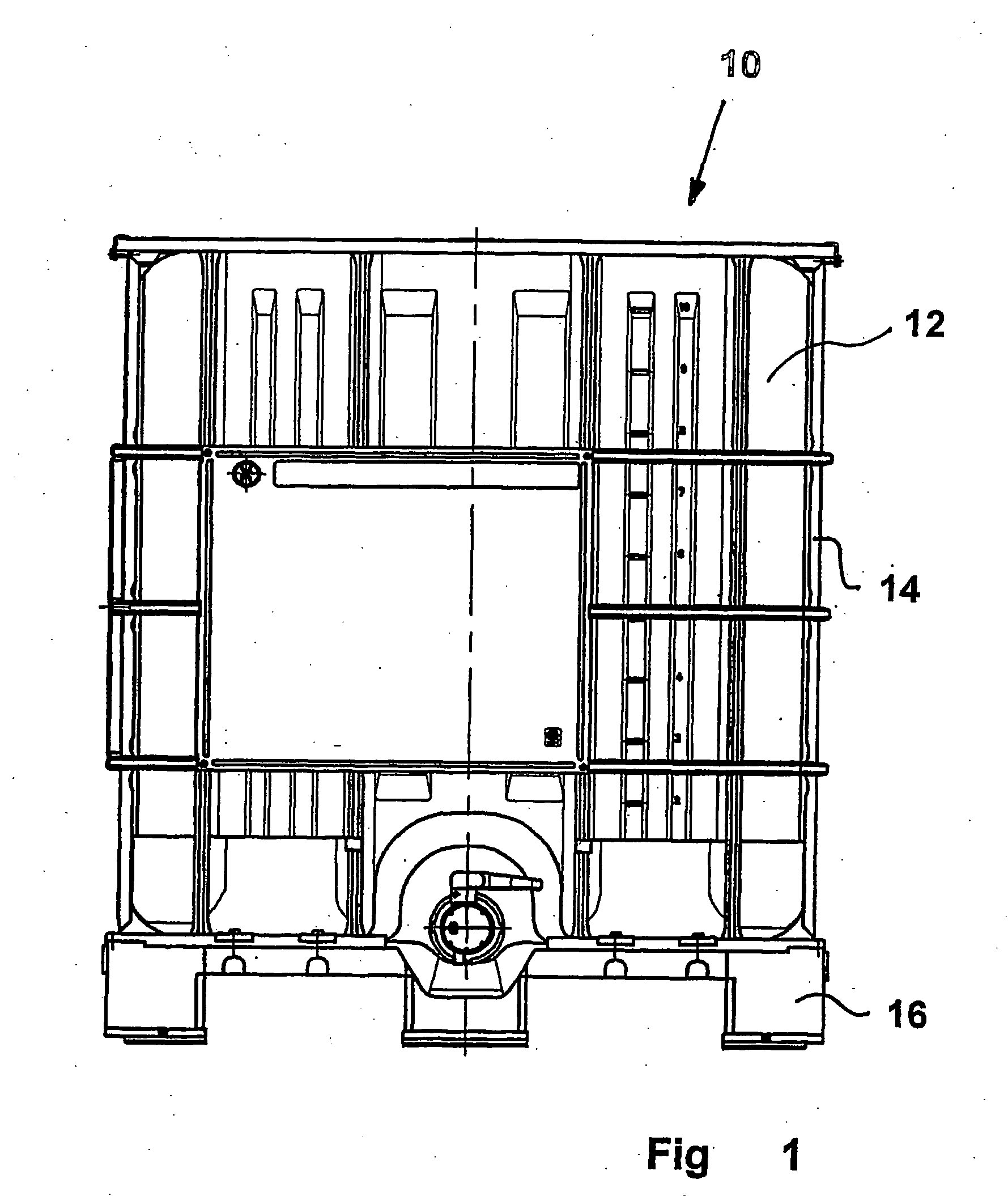
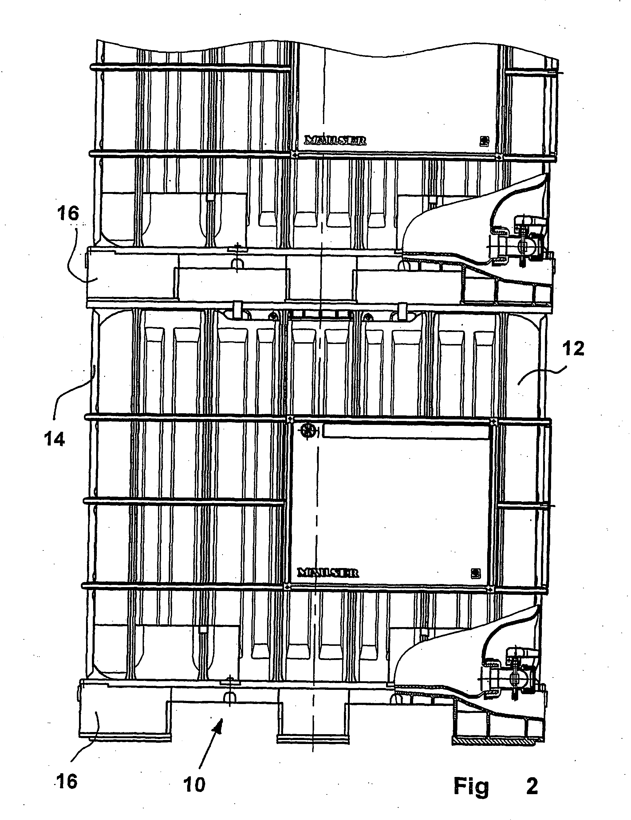
[0054] Throughout all the Figures, same or corresponding elements are generally indicated by same reference numerals. These depicted embodiments are to be understood as illustrative of the invention and not as limiting in any way. It should also be understood that the drawings are not necessarily to scale and that the embodiments are sometimes illustrated by graphic symbols, phantom lines, diagrammatic representations and fragmentary views. In certain instances, details which are not necessary for an understanding of the present invention or which render other details difficult to perceive may have been omitted.

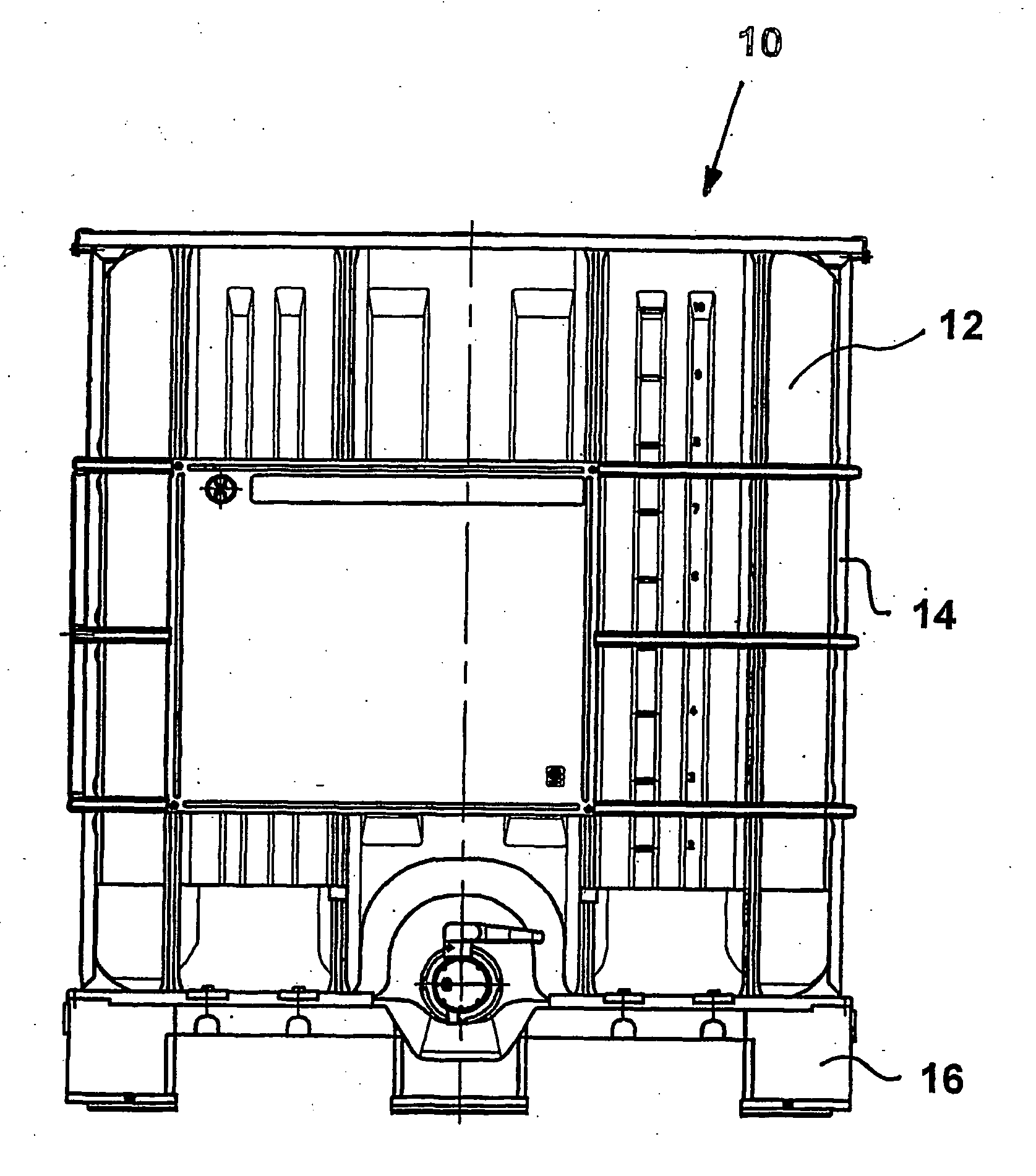
[0055] Turning now to the drawing, and in particular to FIG. 1, there is shown a front view of a pallet container according to the invention, generally designated by reference numeral 10 and including an inner plastic container 12, a lattice tube type support jacket 14, and a bottom pallet 16 with lower discharge fittings. The pallet width may be 1000 mm. As shown in FIG. 2 ...


PUM


Abstract

A pallet container includes a bottom pallet and a thin-walled inner container, made of thermoplastic material and resting on the bottom plate, for storing and transporting liquid or free-flowing goods. Closely surrounding the plastic container is a lattice tube frame which includes vertical and horizontal tubular rods welded to one another and which is securely fixed to the bottom plate. In order to improve the lattice tube frame durability while maintaining sufficient stacking load-bearing capacity, at least the vertical tubular rods have regions of low tubular profile height and high tubular profile height, wherein the regions of low tubular profile height are uniformly linear and positioned outside the intersections, and the regions of high tubular profile height are positioned in an area of the intersections.

Description

CROSS-REFERENCES TO RELATED APPLICATIONS [0001] This application is a continuation of prior filed copending PCT International application no. PCT / EP2004 / 003975, filed Apr. 15, 2004, which designated the United States and on which priority is claimed under 35 U.S.C. §120, and which claims the priority of German Patent Application, Serial No. 203 06 550.6, filed Apr. 25, 2003, pursuant to 35 U.S.C. 119(a)-(d), the subject matter of both are incorporated herein by reference.BACKGROUND OF THE INVENTION [0002] The present invention relates, in general, to a pallet container. [0003] An example of a pallet container of a type involved here has a thin-walled inner container of thermoplastic material for storage and transport of liquid or free-flowing goods. The plastic container is closely surrounded by a lattice tube frame as support jacket, and rests on a bottom pallet to which the support jacket is fixedly secured. The lattice tube frame includes vertical and horizontal tubular rods whic...

Claims


Application Information

Patent Timeline
IPC IPC(8): B65D77/04B65D77/06
CPCB65D77/0466B65D77/06
Inventor PRZYTULLA, DIETMAR
Owner MAUSER WERKE GMBH
Learn More