Automatic swinging drawbar system

Inactive Publication Date: 2005-11-10
SYMINGTON OWEN D
View PDF20 Cites 11 Cited by
  • Summary
  • Abstract
  • Description
  • Claims
  • Application Information

AI Technical Summary

Benefits of technology

[0012] In view of the foregoing disadvantages inherent in the known types of swinging drawbars now present in the prior art, the present invention provides a

Problems solved by technology

The problem with these types of drawbars is that they are not adjustable during operation and they require the operator to leave the tractor cab to manually position the drawbar.
While these hydraulic systems solve the problem of providing adjustability during movement of the tractor, they still require the operator of the tractor to manually operate a hydraulic lever to control the movement of the drawbar.
The problem with leaving the drawbar in a “free” position is that it will violen

Method used


Image

  • Automatic swinging drawbar system
  • Automatic swinging drawbar system
  • Automatic swinging drawbar system

Examples


Embodiment Construction

A. Overview

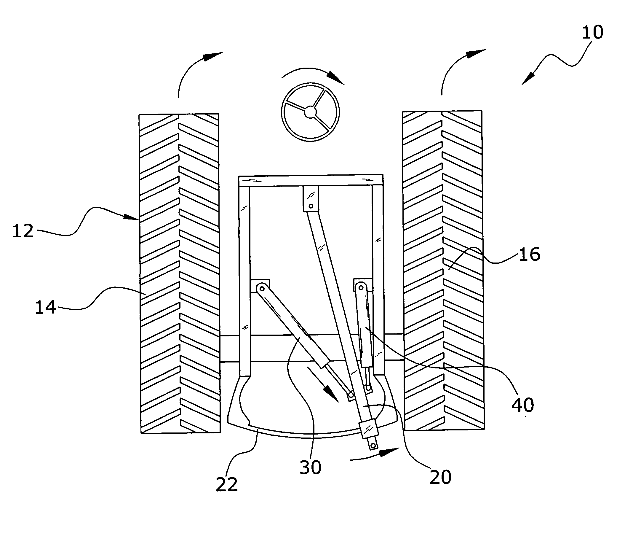
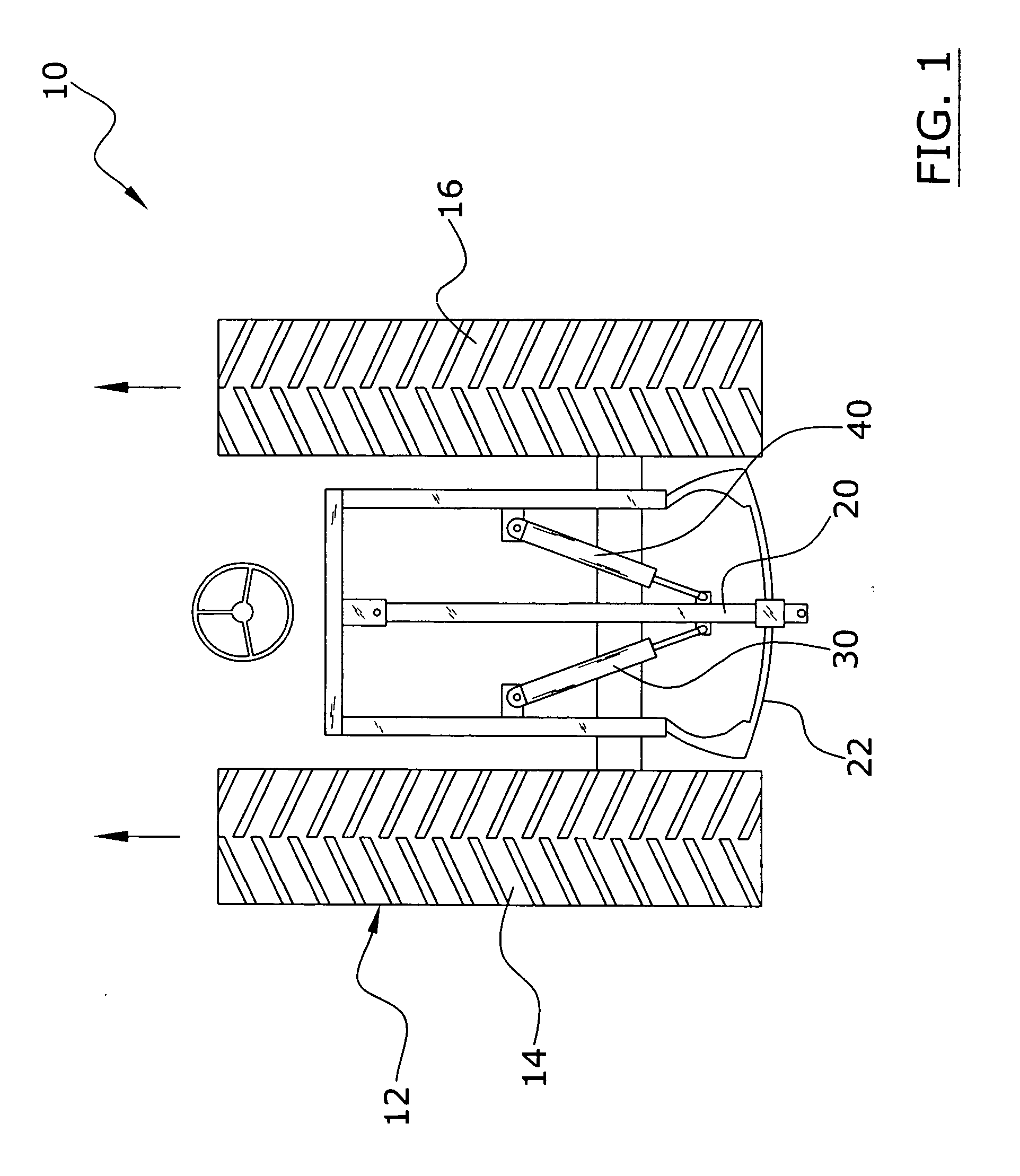
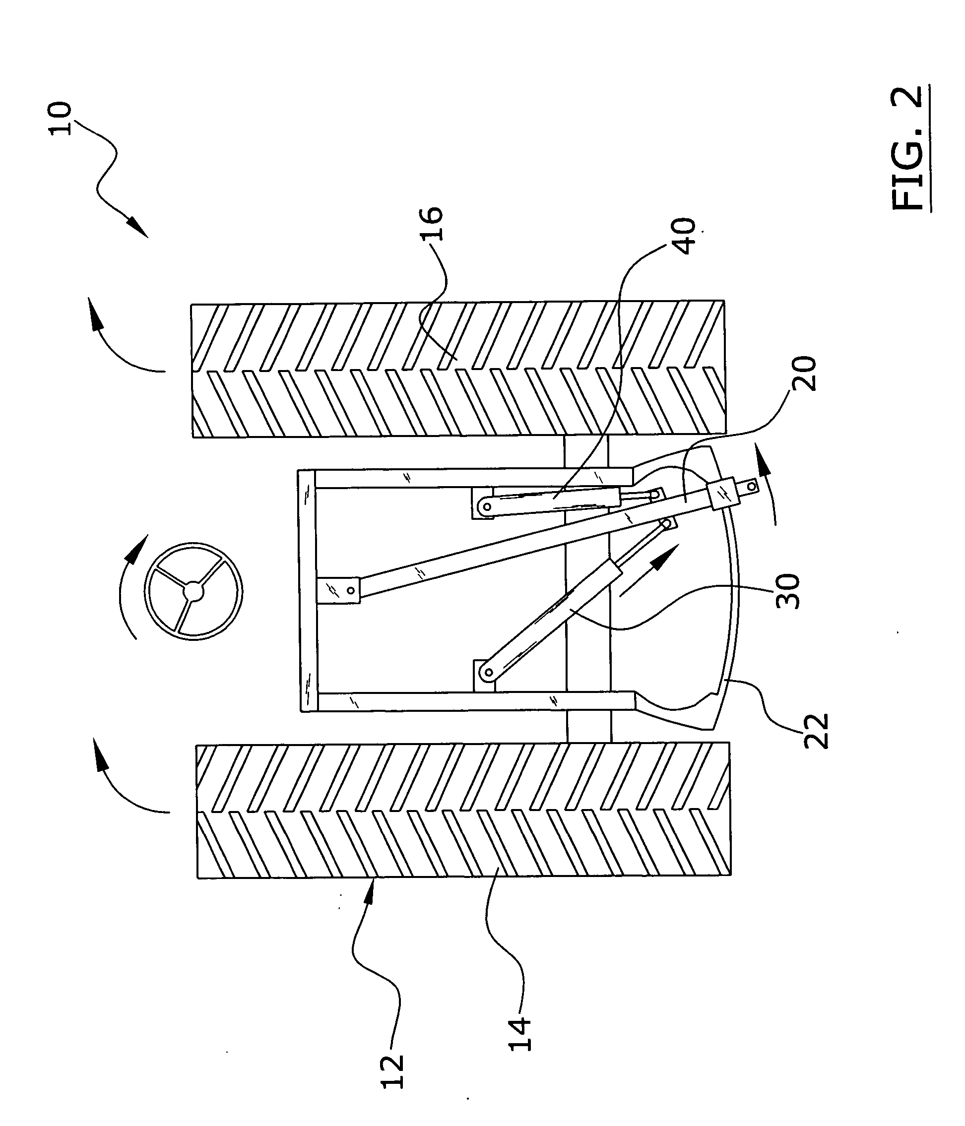
[0033] Turning now descriptively to the drawings, in which similar reference characters denote similar elements throughout the several views, FIGS. 1 through 7 illustrate an automatic swinging drawbar system 10, which comprises a swinging drawbar 20, a first actuators 30 connected to the swinging drawbar 20, a second actuator 40 connected to the swinging drawbars 20, and a control unit 50 for controlling the operation of the actuators 30, 40 to control the rotational position of the swinging drawbar 20. The control unit 50 is in communication with the steering controller of the tractor 12 for monitoring the rotational position and movement of the steering wheel. When the steering wheel is rotated clockwise to turn the tractor 12 to the right, the actuators 30, 40 pivot the swinging drawbar 20 proportionately to the right to increase the steering ability of the tractor 12 pulling an implement. When the steering wheel is rotated counterclockwise to turn the tractor 12 to th...


PUM


Abstract

An automatic swinging drawbar system for efficiently and automatically controlling a tractor's swinging drawbar. The automatic swinging drawbar system includes a swinging drawbar, a first actuator connected to the swinging drawbar, a second actuator connected to the swinging drawbar, and a control unit for controlling the operation of the actuators to control the rotational position of the swinging drawbar. The control unit is in communication with the steering controller of the tractor for monitoring the rotational position and movement of the steering wheel. When the steering wheel is rotated clockwise to turn the tractor to the right, the actuators pivot the swinging drawbar proportionately to the right to increase the steering ability of the tractor pulling an implement. When the steering wheel is rotated counterclockwise to turn the tractor to the left, the actuators pivot the swinging drawbar proportionately to the left.

Description

CROSS REFERENCE TO RELATED APPLICATIONS [0001] Not applicable to this application. STATEMENT REGARDING FEDERALLY SPONSORED RESEARCH OR DEVELOPMENT [0002] Not applicable to this application. BACKGROUND OF THE INVENTION [0003] 1. Field of the Invention [0004] The present invention relates generally to tractor drawbars and more specifically it relates to an automatic swinging drawbar system for efficiently and automatically controlling a tractor's swinging drawbar. [0005] 2. Description of the Related Art [0006] Swinging drawbars have been in use for years on tractors. Conventional swinging drawbars have a drawbar with the front end pivotally attached to the frame of the tractor and slidably supported on a rear support. A conventional swinging drawbar typically has two positions: non-movable and movable. [0007] In the non-movable position, the drawbar is secured in a desired rotational position (e.g. center, to the left, to the right, etc.) which the user typically has to manually posi...

Claims


Application Information

Patent Timeline
IPC IPC(8): B60D1/00B60D1/44B60D1/58
CPCB60D1/58B60D1/44
Inventor SYMINGTON, OWEN D.
Owner SYMINGTON OWEN D
Why Eureka
Try Eureka