Motor control device and motor-driven power steering system using the same

a technology of motor control device and power steering system, which is applied in the direction of electric generator control, dynamo-electric converter control, dynamo-electric gear control, etc., can solve the problems of hindering the enhancement of motor output and ineffective use of voltage, so as to achieve effective use of power supply voltage, suppress torque fluctuation, and effect of using power supply

Active Publication Date: 2011-12-20
NSK LTD
View PDF15 Cites 19 Cited by
  • Summary
  • Abstract
  • Description
  • Claims
  • Application Information

AI Technical Summary

Benefits of technology

[0019]In the invention, the phase currents iu, iv and iw are determined so as to make Tωm on the left-hand side of the energy balance equation in the above Eq. (1) constant, enabling calculation of phase current command values that do not cause torque fluctuation, and the absolute value of a composite vector of drive voltages for the respective phases is substantially constant and substantially corresponds to a value √3 / 2 times the power supply voltage, enabling effective use of a power supply voltage VR supplied from the motor drive circuit to the three-phase brushless motor. In other words, the voltage that can be applied to the U, V and W phases of the three-phase brushless motor is 0 to VR, and when each phase is expressed by a voltage vector, as shown in FIG. 23, phase voltages Vu, Vv and Vw are expressed by three phase vectors shifted from each other by 120 degrees. The voltage vector range that may be taken by the composite vector of these phase voltages Vu, Vv and Vw is the hatched area in FIG. 23, and the range in this area that can make the absolute value of the composite vector constant is within a range of up to power supply voltage×√3 / 2. Thus, the absolute value of the composite vector is set to a value in the neighborhood of a value √3 / 2 times the power supply voltage including the value √3 / 2 times the power supply voltage, enabling provision of a constant absolute value for the composite vector and effective use of the power supply voltage.
[0069]Also, an advantageous effect can be obtained in that favorable steering performance can be provided by controlling the driving of an electric motor that generates a steering auxiliary force for a motor-driven power steering system, via the aforementioned motor drive control device.

Problems solved by technology

However, the aforementioned conventional art example has an outstanding problem in that when the torque of a harmonic motor is controlled to be constant, the motor drive voltage waveforms necessary for applying the currents are substantially distorted according to the harmonic waves of the induced voltages, and as a result, the power supply voltage cannot effectively be used, hindering enhancement of the motor output.

Method used


Image

  • Motor control device and motor-driven power steering system using the same
  • Motor control device and motor-driven power steering system using the same
  • Motor control device and motor-driven power steering system using the same

Examples


first embodiment

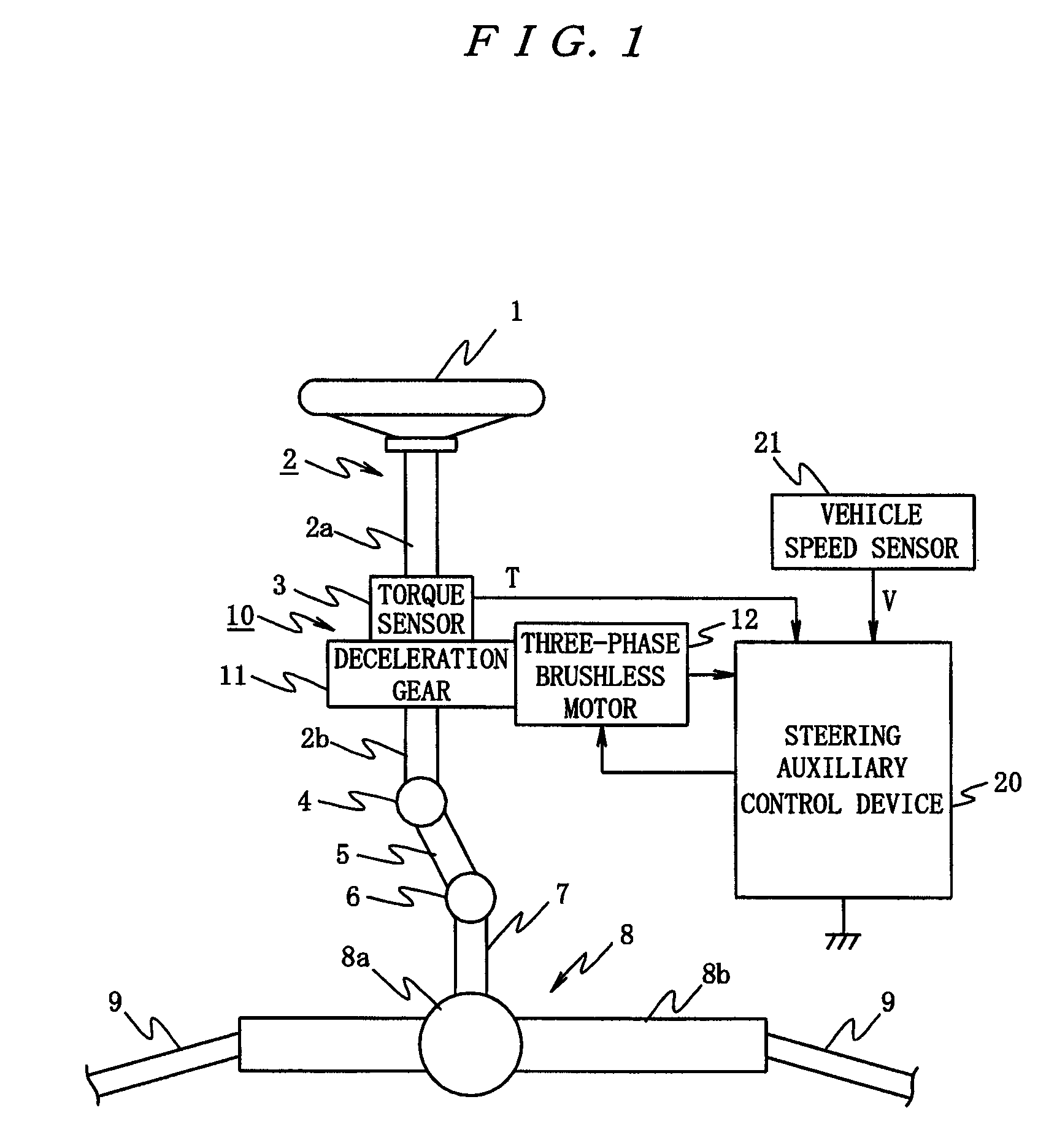
[0102]FIG. 1 is an overall configuration of a first embodiment where the present invention is employed in a motor-driven power steering system, and in the Figure, reference numeral 1 denotes a steering wheel, and a steering force exerted by a driver to the steering wheel 1 is conveyed to a steering shaft 2 having an input shaft 2a and an output shaft 2b. One end of the input shaft 2a of this steering shaft 2 is connected to the steering wheel 1, and the other end is connected via a steering torque sensor 3 to one end of the output shaft 2b as steering torque detection means.

[0103]The steering force conveyed to the output shaft 2b is conveyed via a universal joint 4 to a lower shaft 5, and is further conveyed via a universal joint 6 to a pinion shaft 7. The steering force conveyed to this pinion shaft 7 is conveyed via a steering gear 8 to a tie rod 9 to turn steered wheels not shown. Here, the steering gear 8 is configured to have a rack-and-pinion structure having a pinion 8a conne...

second embodiment

[0168]Next, the present invention will be described with reference to FIGS. 24 to 27.

[0169]In this second embodiment, to the steering auxiliary control device 20 in the first embodiment, a steering torque T detected by the steering torque sensor 3 and a vehicle speed V detected by the vehicle speed sensor 21 are input, and also an angle detection signal θm detected by the motor position detection circuit 13 is input, and based on this angle detection signal θm, an electrical angle θe output from an electrical angle calculation unit 50 that calculates an electrical angle θe is input, and furthermore, motor drive current detection values Iadet and Icdet output from a motor current detection unit 57 that detects, in the later-described inverter circuit 56, motor drive currents Ia and Ic supplied to phase coils La and Lc in the three-phase brushless motor 12, and Ibdet estimated from the motor drive currents Ia and Ic are input.

[0170]This steering auxiliary control device 20, as shown i...

third embodiment

[0233]Next, the present invention will be described with reference to FIG. 28.

[0234]This third embodiment reduces an back electromotive voltage compensation error where the back electromotive voltage compensation error due to back electromotive voltage distortion significantly increases at a high rotation speed and a high current, in addition to the generation of current command values in conformity to distorted back electromotive voltages to provide a constant torque in the aforementioned second embodiment.

[0235]In other words, in the third embodiment, a control device 20, as shown in FIG. 28, includes an angular velocity calculation unit 80, a current command value generation unit 81, a d-q axis current command value calculation unit 82, a two-phase / three-phase conversion unit 83, a compensation back electromotive voltage calculation unit 84, a current control unit 85, an adder unit 86, a PWM control unit 87, and an inverter circuit 88.

[0236]The angular velocity calculation unit 8...


PUM


Abstract

An object of the present invention is to provide a motor control device capable of suppressing voltage composite vector fluctuation to increase the output of a brushless motor, and a motor-driven power steering system using this device. The present control device calculates motor phase current command values based on a target current and a rotor rotational position detection value, calculates voltage command values based on the motor phase current command values and phase current detection values, and supplies phase currents to a three-phase brushless motor based on the voltage command values. The present control device outputs the phase current command values so that the absolute value of a composite vector of respective phase drive voltages is substantially a value √3 / 2 times the power supply voltage.

Description

TECHNICAL FIELD[0001]The present invention relates to a motor control device for controlling a three-phase brushless motor with back electromotive voltages having harmonic components superimposed therein, i.e., what is called a harmonic motor, and to a motor-driven power steering system using the motor control device.BACKGROUND ART[0002]As a control device for this kind of three-phase brushless motor with induced voltages having harmonic components superimposed therein, for example, a motor drive control device proposed by the present applicant in the past, which comprises: a vector control phase command value calculation unit that calculates a phase current command value for each phase of a motor using vector control; a motor current detection unit that detects a motor phase current for each phase of the motor; and a current control unit that controls phase currents of the motor based on the phase current command values and the motor phase currents, wherein the vector control phase...

Claims


Application Information

Patent Timeline
Patent Type & Authority Patents(United States)
IPC IPC(8): H02P6/10H02P27/04B62D5/04H02P6/06H02P6/08H02P6/28H02P21/00H02P21/05H02P21/13H02P21/22H02P23/04H02P27/08
CPCB62D5/046H02P6/10
Inventor MIURA, TOMOHIROMAEDA, MASAHIROIMAMURA, YOUSUKEKOVUDHIKULRUNGSRI, LILIT
Owner NSK LTD
Why Eureka
Try Eureka