Distribution apparatus

a technology of distribution apparatus and distributor, which is applied in the direction of charging/discharging current/voltage regulation, emergency protective arrangements for limiting excess voltage/current, transportation and packaging, etc., can solve the problem of excessive current, risk of abnormal current flowing in the distributor situated in the aircraft, and does not consider effective use of the regenerative power generated by the electric actuator. , to achieve the effect of efficient power use in the aircra

Active Publication Date: 2017-01-24
NABLESCO CORP
View PDF9 Cites 2 Cited by
  • Summary
  • Abstract
  • Description
  • Claims
  • Application Information

AI Technical Summary

Benefits of technology

[0007]The present invention has been developed in light of the aforementioned circumstances to provide a distribution apparatus in which there is little abnormality resultant from an excessively large current. The distribution apparatus may achieve efficient power use in an aircraft.
[0009]The aforementioned distribution apparatus may use power efficiently in an aircraft with causing little abnormality in the distributor.

Problems solved by technology

In short, JP 2007-46790 A does not consider effective usage of the regenerative power generated by the electric actuator.
However, there may be an excessively large current if shorting or alike causes faults in the electric actuator.
If regenerative power is sent to a distributor as described above, there is a risk of an abnormal current flowing in the distributor situated in the aircraft.
There is also a risk of an abnormal current (excessively large current) flowing to the distributor resultant from a surge current caused by a lightning strike on the aircraft or alike.

Method used


Image

  • Distribution apparatus
  • Distribution apparatus
  • Distribution apparatus

Examples


first embodiment

[0021]An exemplary embodiment of a power system is described below with reference to the drawings.

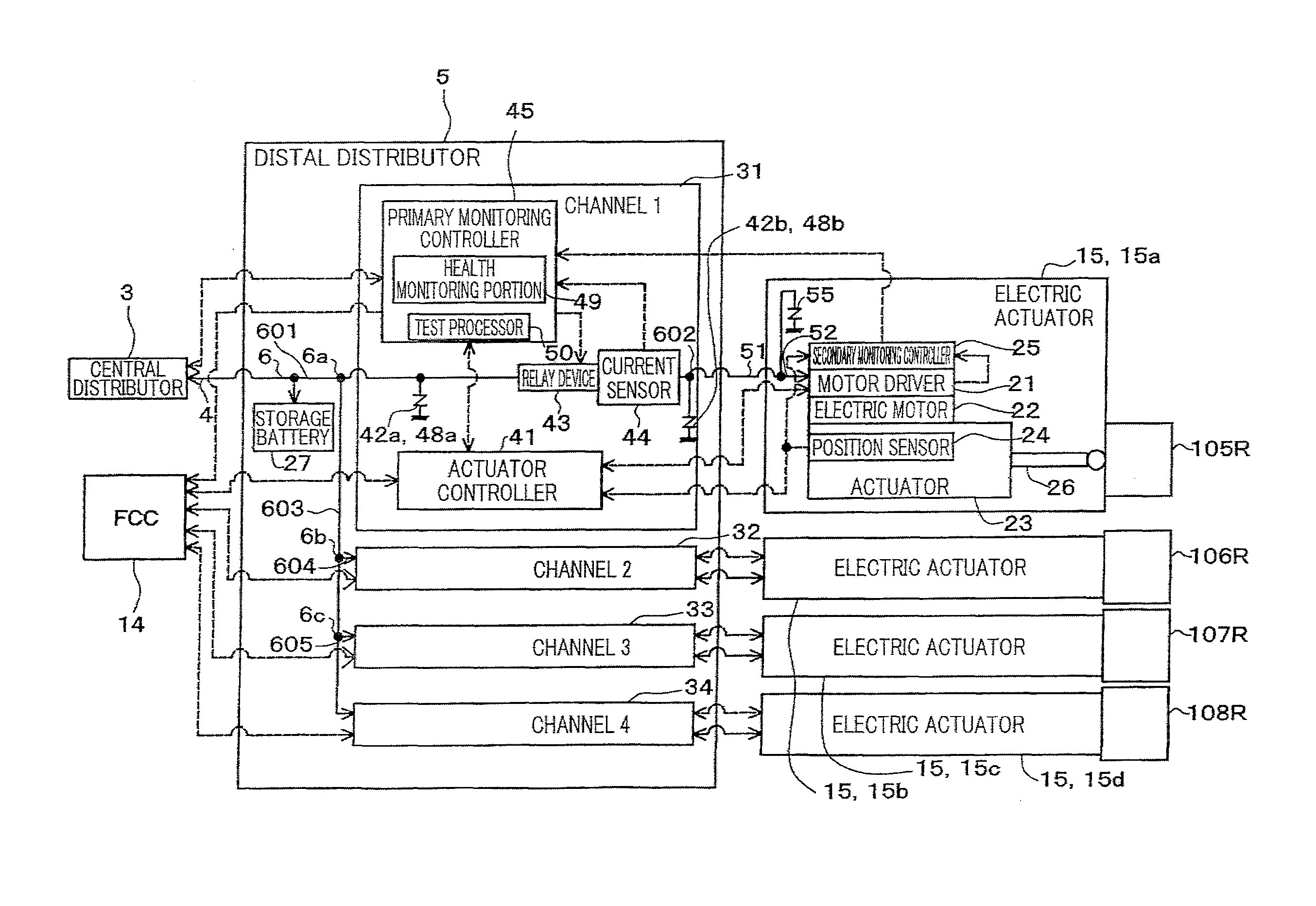
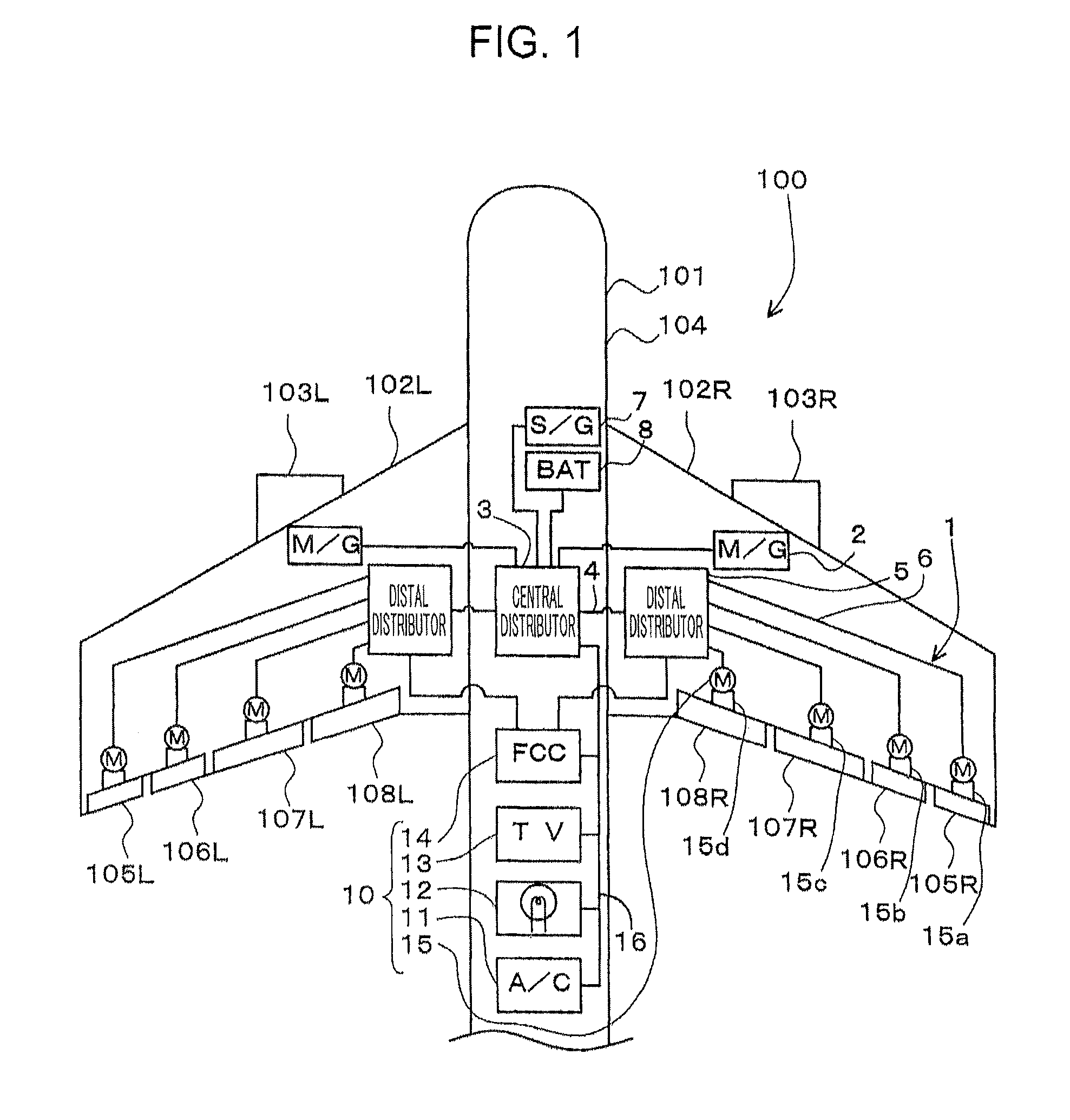
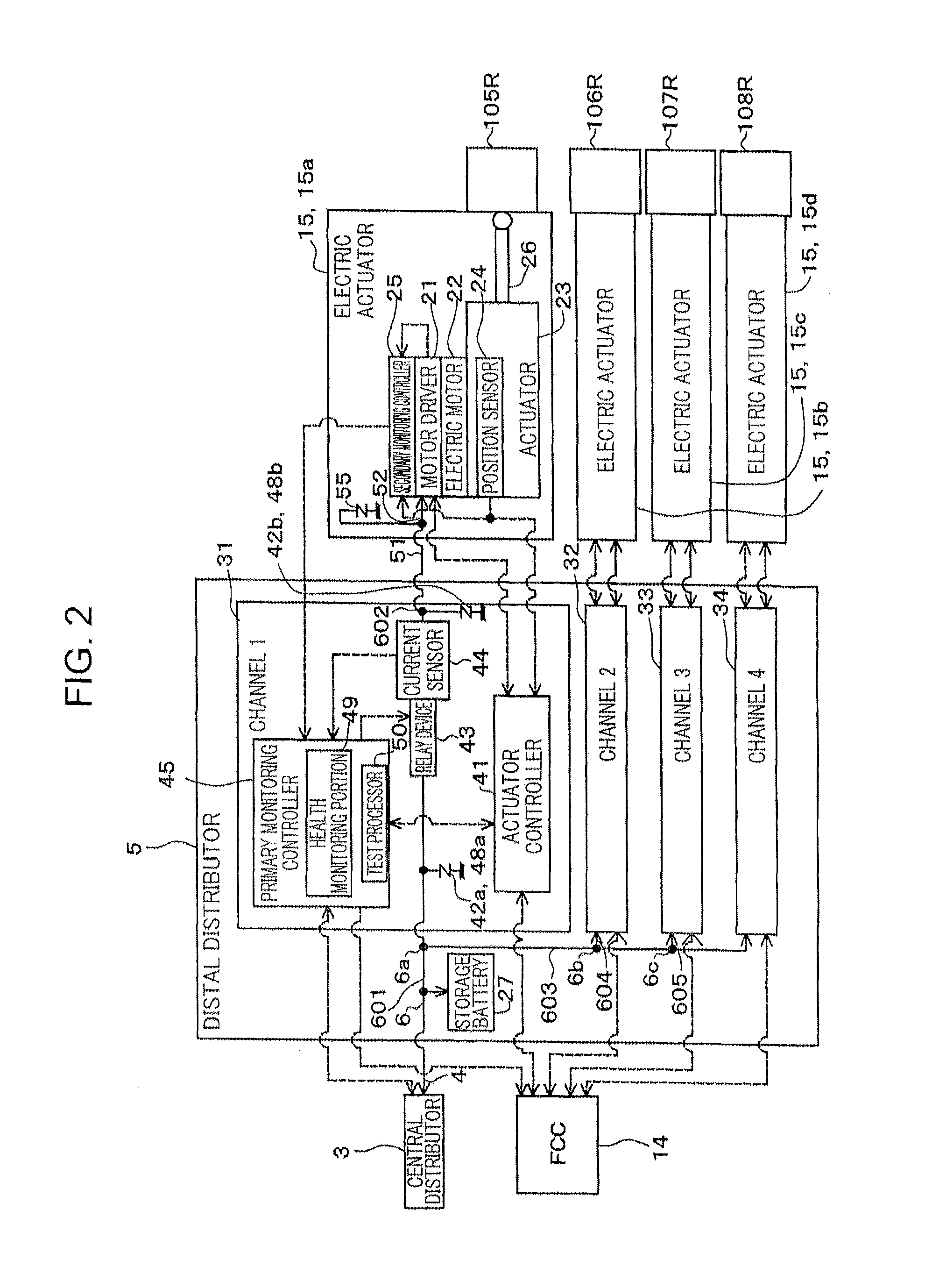
[0022]FIG. 1 is a schematic view showing a part of an aircraft 100 having the exemplary power system 1 according to the first embodiment. FIG. 1 shows a front portion and a middle portion of a body 101 of an aircraft 100. A rear portion of the body 101 is not shown in FIG. 1. FIG. 2 is a schematic view of a main part of the power system 1.

[0023]The wires indicated in FIG. 2 by solid lines are power wires (high-voltage wires) which supply power in order to mechanically operate the electric actuators 15. On the other hand, the wires indicated in FIG. 2 by dotted lines are signal wires (low-voltage wires) for controlling the electric actuators 15.

[0024]As shown in FIG. 1, for example, the aircraft 100 may be a passenger plane. The aircraft 100 includes a body 101, a pair of left and right engines 103L, 103R, and the power system 1.

[0025]The body 101 includes a fuselage 104, and a pair of l...

modification examples

[0126]Various modifications may be applied to the aforementioned embodiment. Various modifications are described below.

[0127](1) In the aforementioned embodiment, the lightning surge protectors 42a, 42b are situated in the channels 31, 32, 33, 34. Alternatively, the lightning surge protectors 42a, 42b may be omitted. There may be only one lightning surge protector situated in the distal distributor 5. In this case, the lightning surge protector in the first portion 601 of the second power source wire 6 is situated, for example, between the storage battery 27 and the bifurcation 6a.

[0128](2) In the aforementioned embodiment, the electric actuators 15 are connected to the distal distributor 5. Alternatively, electrical devices other than the electric actuators 15 may be connected to the distal distributor 5.

[0129](3) In the aforementioned embodiment, a channel is provided for each of the electric actuators 15. Alternatively, one channel 31 may simultaneously control the electric actu...


PUM


Abstract

Disclosed herein is an invention of a power system including a distal distributor, an electric actuator which receives a supply of power from the distal distributor, and a relay device. Regenerative power generated by the electric actuator is output to a storage battery.

Description

TECHNICAL FIELD[0001]The present invention relates to a distribution apparatus to which an electric actuator and a storage battery are connected.BACKGROUND ART[0002]An aircraft has various electrically powered devices. For example, such devices are driven by electric motors mounted in the aircraft. An example of such devices is an electrically powered hydraulic pump for supplying hydraulic oil to a hydraulically operated actuator which drives a movable wing, as disclosed in JP 2007-46790 A.[0003]The movable wings are primary control surfaces which are constituted as rudder surfaces such as auxiliary wings (ailerons), rudders and elevators, or secondary control surfaces which are constituted as flaps, spoilers, and the like. Another example of the devices includes an electric actuator which drives the movable wings or legs such as landing gear (a mechanism supporting the body of the aircraft on the ground) or alike.[0004]For example, the electric actuator which serves as an actuator ...

Claims


Application Information

Patent Timeline
Patent Type & Authority Patents(United States)
IPC IPC(8): H02J7/00B64D41/00H02H3/08H02H9/04H02J1/00H02J7/34H02P29/00
CPCH02J7/007H02J7/0052H02J1/10H02J7/34H02J7/345H02H3/20H02H9/041B64D2221/00H02J2310/44Y02T50/40
Inventor YASUI, TSUTOMU
Owner NABLESCO CORP
Why Eureka
Try Eureka