
Method for airbag inflation control

a technology of airbag inflation and control, which is applied in the direction of pedestrian/occupant safety arrangement, vehicular safety arrangment, vehicle components, etc., can solve the problems of occupants not being positioned appropriately, and the deployment event itself is likely to cause more serious injuries for the occupants

Inactive Publication Date: 2005-11-10
AMERICAN VEHICULAR SCI
View PDF28 Cites 53 Cited by
  • Summary
  • Abstract
  • Description
  • Claims
  • Application Information

AI Technical Summary

Benefits of technology

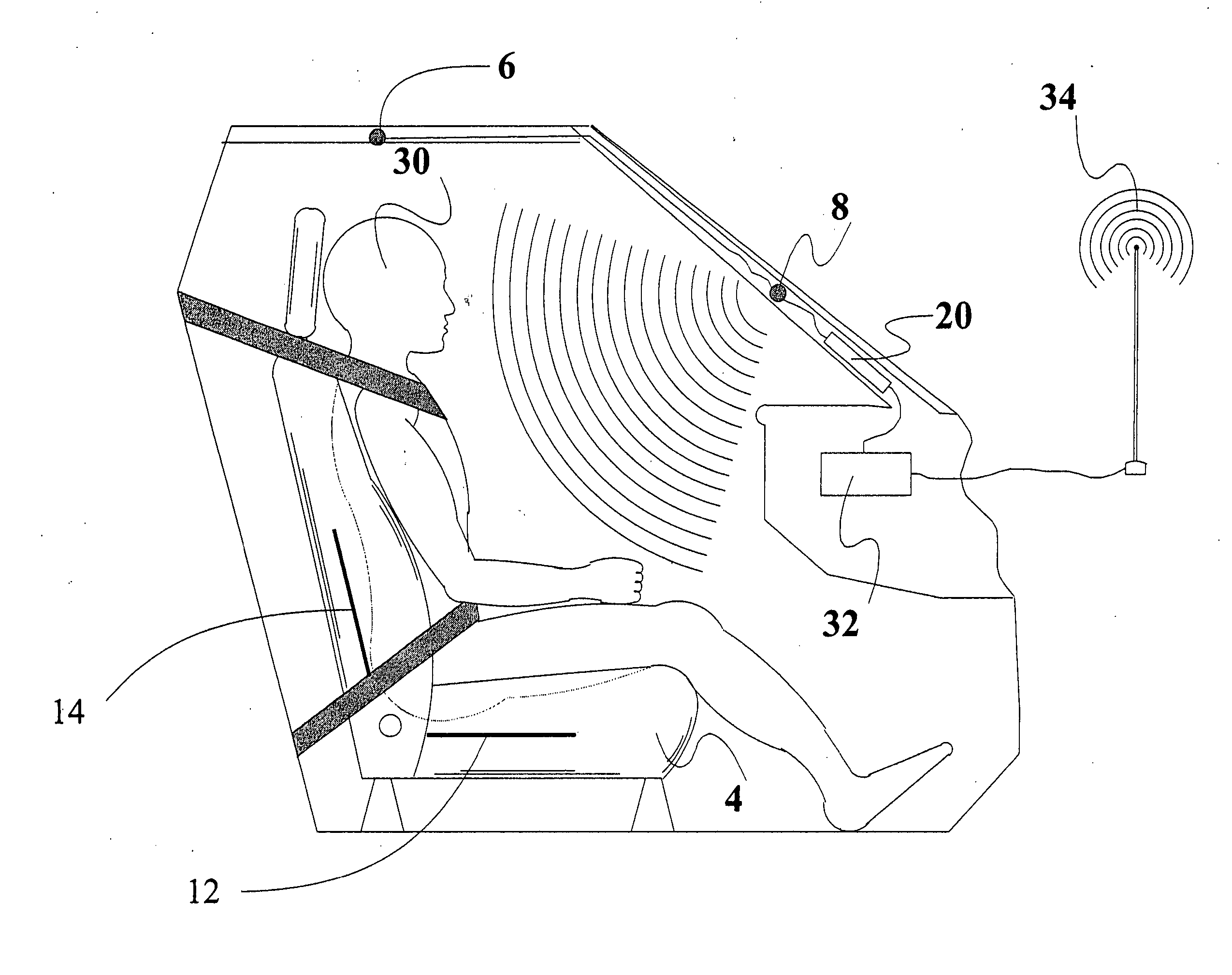
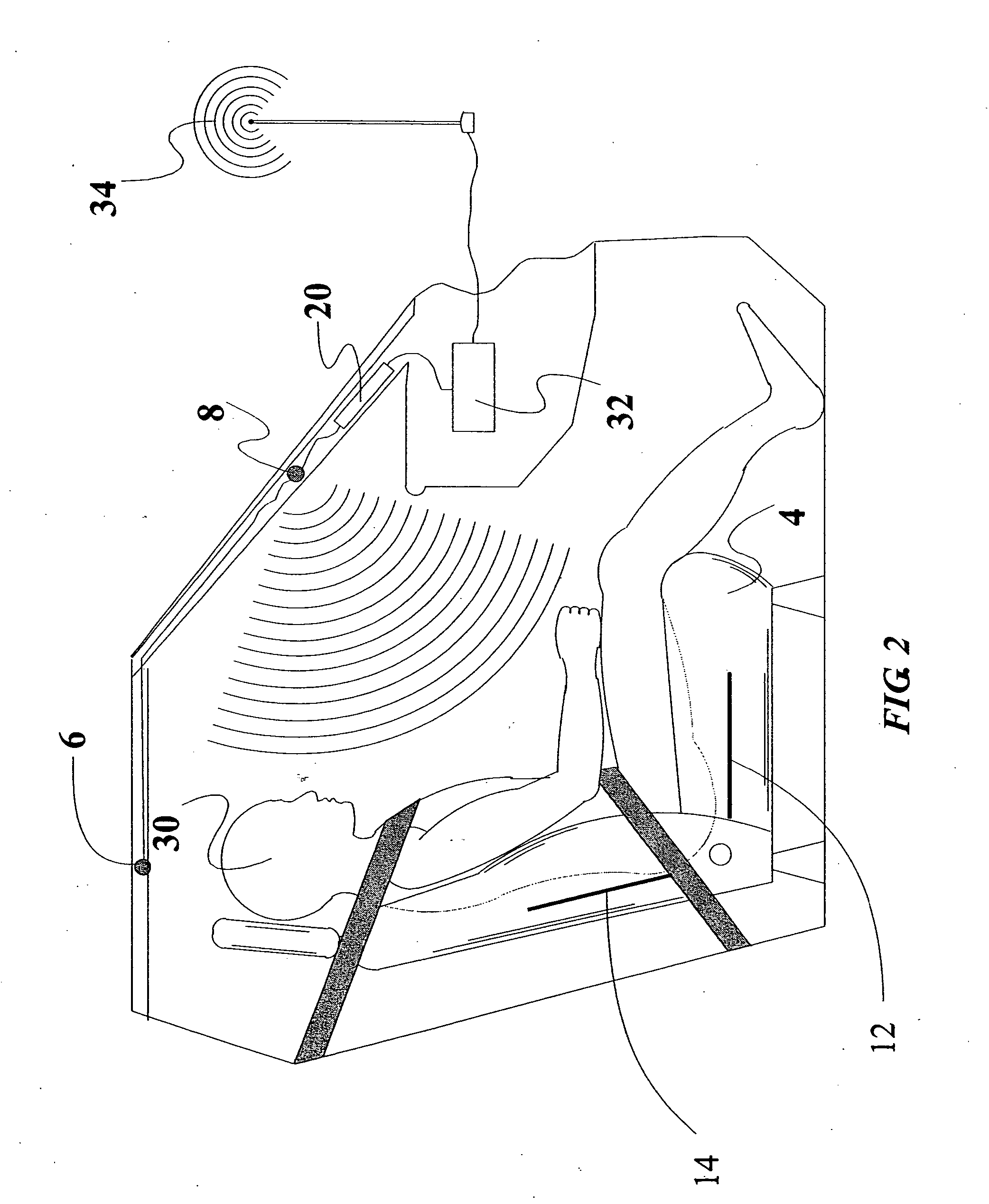
[0080] The invention also includes methods and arrangements for obtaining information about an object in a vehicle. This determination is used in various methods and arrangements for, e.g., controlling occupant protection devices in the event of a vehicle crash. The determination can also used in various methods and arrangements for, e.g., controlling heating and air-conditioning systems to optimize the comfort for any occupants, controlling an entertainment system as desired by the occupants, controlling a glare prevention device for the occupants, preventing accidents by a driver who is unable to safely drive the vehicle and enabling an effective and optimal response in the event of a crash (either oral directions to be communicated to the occupants or the dispatch of personnel to aid the occupants). Thus, one objective of the invention is to obtain information about occupancy of a vehicle and convey this information to remotely situated assistance personnel to optimize their response to a crash involving the vehicle and / or enable proper assistance to be rendered to the occupant(s) after the crash.
[0083] To provide a reliable system for determining the position, velocity or size of an occupant in a motor vehicle.
[0090] It is an object of the present invention to provide new and improved arrangements and methods for adjusting or controlling a component in a vehicle based on occupancy of the vehicle. Control of a component does not require an adjustment of the component if the operation of the component is appropriate for the situation. For example, an airbag system may be controlled based on the location of a seat and the occupant of the seat to be protected by the deployment of the airbag.
[0092] To provide a system for automatically adjusting the position of various components of the vehicle to permit safer and more effective operation of the vehicle including the location of the pedals and steering wheel.
[0097] To adjust the flow of gas into and / or out of the airbag based on the morphology and / or position of the occupant to improve the performance of the airbag in reducing occupant injury. SUMMARY OF THE INVENTION
[0099] Adjustment of the amount of gas within the airbag may entail varying the amount of gas being directed into the airbag based on the size of the occupant, e.g., reducing the amount of gas when the detected position of the occupant is indicative of a small occupant or an occupant positioned close to a compartment in which the airbag is stored, or increasing the amount of gas being directed into the airbag when the detected position of the occupant is indicative of a large occupant. Additionally or alternatively, adjustment of the amount of gas may entail controlling the outflow of gas from the airbag based on the size of the occupant, e.g., reducing the size of at least one gas exit passage formed in association with the airbag when the detected position of the occupant is indicative of a large occupant or increasing of the size of at least one gas exit passage formed in association with the airbag when the detected position of the occupant is indicative of a small occupant. Thus, the airbag can be vented, to control the pressure therein, through at least one gas exit passage formed in the airbag material. Additionally or alternatively, an exit control valve may be arranged adjacent the inflator and in fluid communication with the airbag and controlled to provide an opening through which gas flows.

Problems solved by technology

“Out-of-position” as used for an occupant will generally mean that the occupant, either the driver or a passenger, is sufficiently close to an occupant protection apparatus (airbag) prior to deployment that he or she is likely to be more seriously injured by the deployment event itself than by the accident.
It may also mean that the occupant is not positioned appropriately in order to attain the beneficial, restraining effects of the deployment of the airbag.

Method used


Image

  • Method for airbag inflation control
  • Method for airbag inflation control
  • Method for airbag inflation control

Examples


Embodiment Construction

[0205] Note whenever a patent or literature is referred to below it is to be assumed that all of that patent or literature is to be incorporated by reference in its entirety to the extent the disclosure of these reference is necessary. Also note that although many of the examples below relate to a particular vehicle, an automobile, the invention is not limited to any particular vehicle and is thus applicable to all relevant vehicles including shipping containers and truck trailers and to all compartments of a vehicle including, for example, the passenger compartment and the trunk of an automobile or truck.

1. General Occupant Sensors

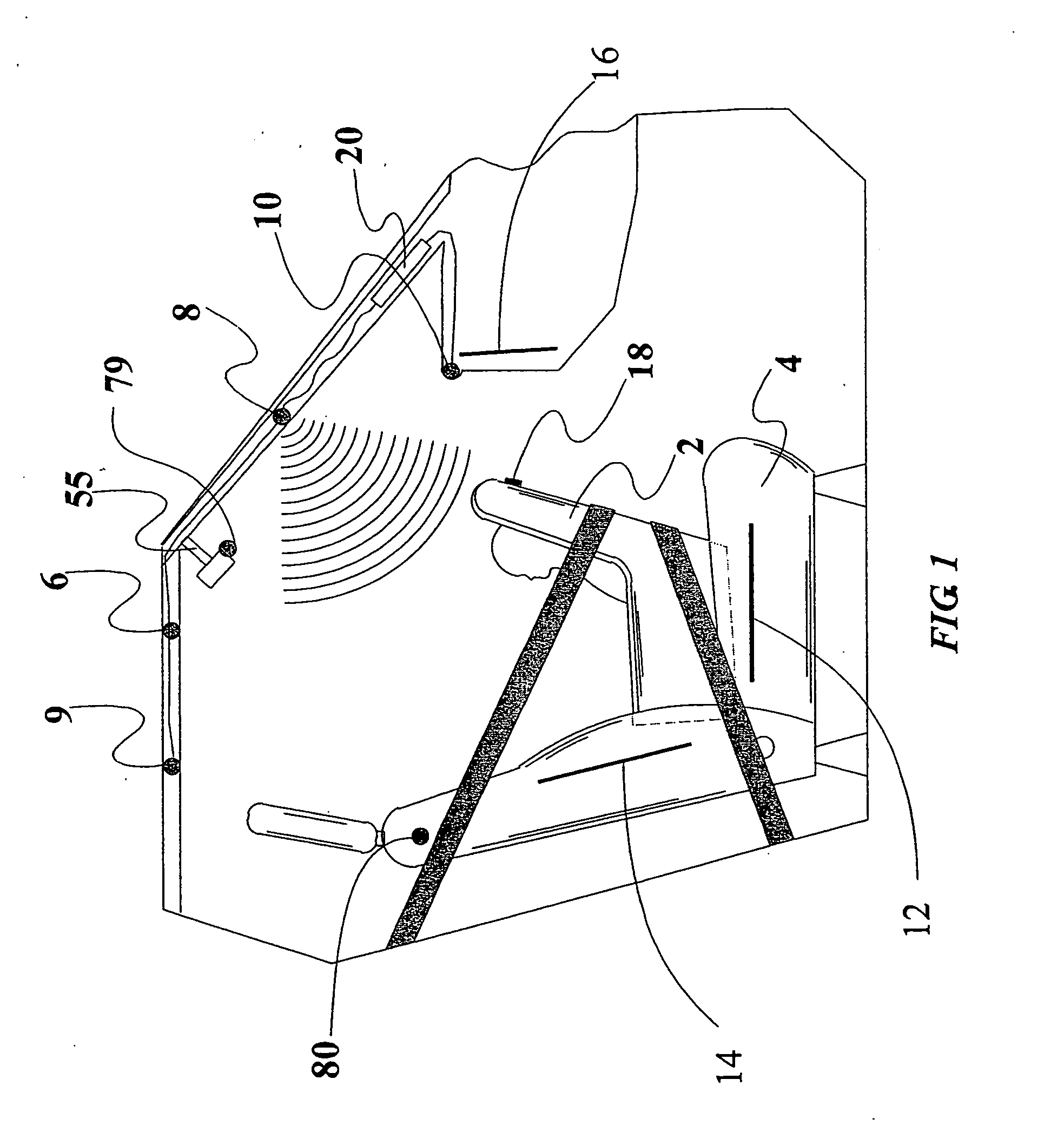
[0206] Referring to the accompanying drawings, FIG. 1 is a side view, with parts cutaway and removed of a vehicle showing the passenger compartment, or passenger container, containing a rear facing child seat 2 on a front passenger seat 4 and a preferred mounting location for a first embodiment of a vehicle interior monitoring system in accordance with...


PUM


Abstract

Method for controlling deployment of an airbag into a passenger compartment of a vehicle including detecting a position of an occupant whose forward-facing surface will be the surface which interacts with the airbag upon its deployment, determining a desired amount of gas within the airbag during inflation of the airbag based at least in part on the detected position of the occupant, and adjusting the amount of gas within the airbag during inflation of the airbag to provide the airbag with the desired amount of gas during its inflation. Adjustment of the amount of gas within the airbag may entail varying the amount of gas being directed into the airbag based on the morphology of the occupant (inflow control) and / or controlling the outflow of gas from the airbag based on the morphology of the occupant (outflow control).

Description

CROSS REFERENCE TO RELATED APPLICATIONS [0001] This application is a divisional of U.S. patent application Ser. No. 10 / 931,288 which is: [0002] 1) a continuation-in-part of U.S. patent application Ser. No. 10 / 174,803 filed Jun. 19, 2002 which is a continuation-in-part of: [0003] a) U.S. patent application Ser. No. 09 / 500,346 filed Feb. 8, 2000, now U.S. Pat. No. 6,442,504, which is a continuation-in-part of U.S. patent application Ser. No. 09 / 128,490, now U.S. Pat. No. 6,078,854, which is a continuation-in-part of: [0004] 1) U.S. patent application Ser. No. 08 / 474,783 filed Jun. 7, 1995, now U.S. Pat. Nos. 5,822,707, and [0005] 2) U.S. patent application Ser. No. 08 / 970,822 filed Nov. 14, 1997, now U.S. Pat. No. 6,081,757; [0006] b) U.S. patent application Ser. No. 09 / 849,558 filed May 4, 2001, now U.S. Pat. No. 6,653,577, which is a continuation-in-part of U.S. patent application Ser. No. 09 / 193,209 filed Nov. 17, 1998, now U.S. Pat. No. 6,242,701, which is a continuation-in-part o...

Claims


Application Information

Patent Timeline
IPC IPC(8): B60R21/01B60R21/015B60R21/26
CPCB60R2021/01225B60R21/0153B60R21/0152
Inventor BREED, DAVID S.DU VALL, WILBUR E.JOHNSON, WENDELL C.
Owner AMERICAN VEHICULAR SCI
Learn More