
Camera device with unitary interface cabling

Inactive Publication Date: 2005-11-10
I3 INT INC
View PDF2 Cites 19 Cited by
  • Summary
  • Abstract
  • Description
  • Claims
  • Application Information

AI Technical Summary

Benefits of technology

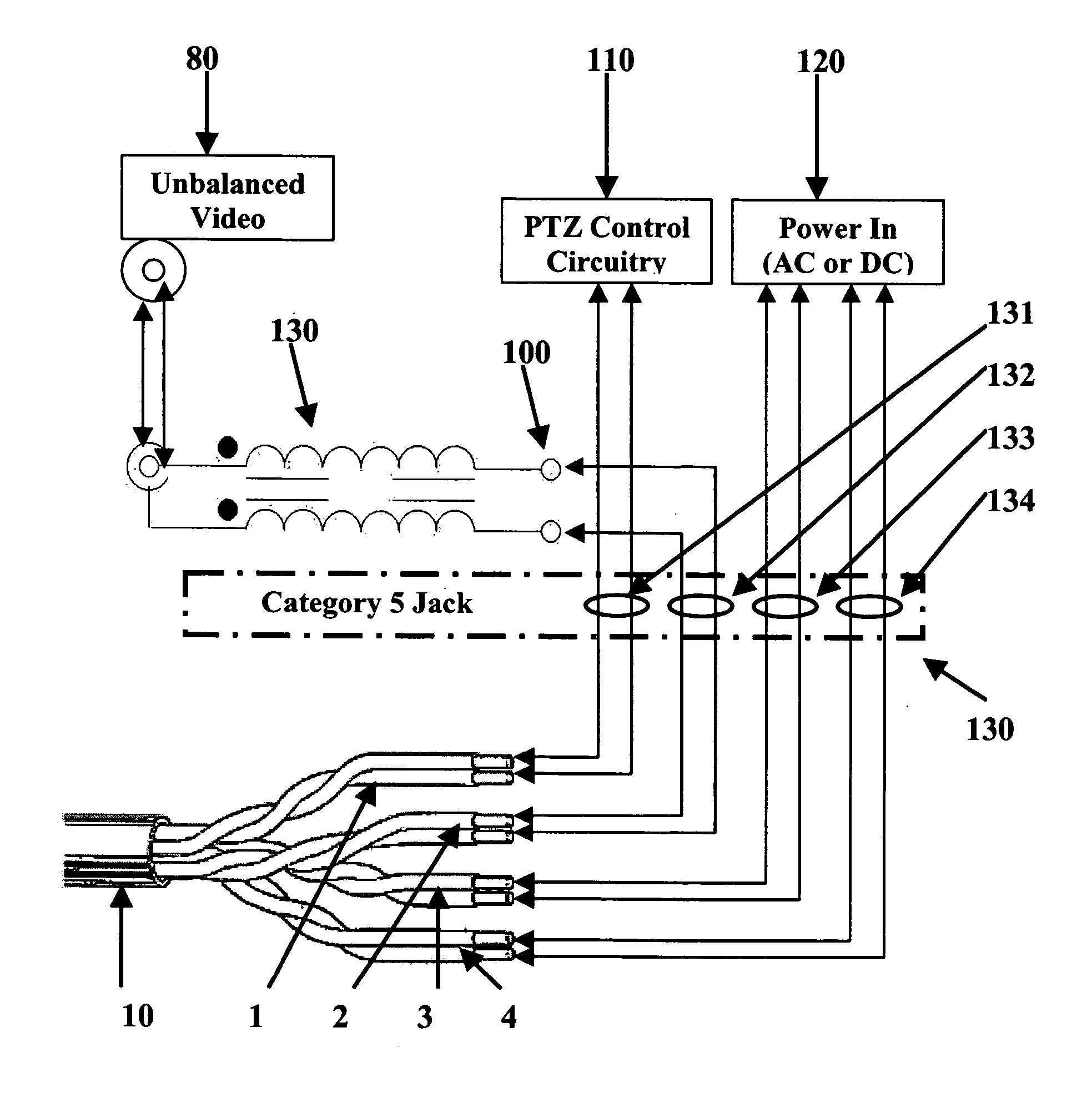
[0013] This invention provides a camera device with greatly reduced wire requirements with acceptable loss ratios for ranges up to 1000 feet using category 5 network cable without additional amplification. The camera connection is much simpler, and the signal is easily reconverted using another balun at the receiving end of the category 5 network cable. The modification of existing video cameras to transmit power, video and control signals over standard network cabling creates a useful standard for digital surveillance video management systems.

Problems solved by technology

RG58, RG59 or RG6 co-axial cables have the disadvantage of requiring amplification for longer distances (over a few hundred feet) due to loss of high frequency signal drop.
Such a system would be cumbersome and costly to install and manage.

Method used


Image

  • Camera device with unitary interface cabling
  • Camera device with unitary interface cabling
  • Camera device with unitary interface cabling

Examples


Embodiment Construction

[0017] A detailed description of the embodiments of the invention will now be provided with specific reference to the drawing illustrating a preferred embodiment of the invention. Like structures will be provided with like reference numbers.

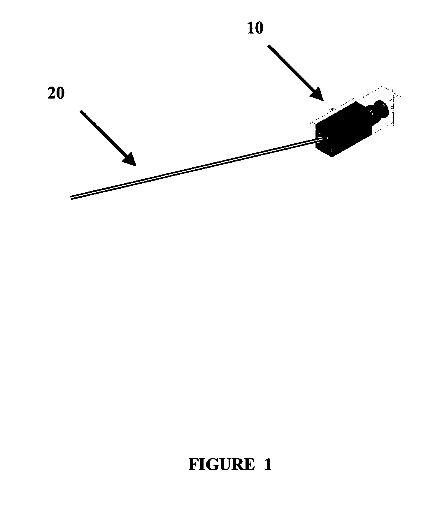
[0018]FIG. 1 is a perspective rear view of a preferred embodiment of the invention showing a single interface cable 20 connected to a camera system 10 of the subject invention. The interface cable 20 is preferably a category 5 cable with 4 twisted pairs of wiring. Higher grade network cabling can also be used in the spirit of the immediate invention, with modifications to the connection interface, or by using adapters to convert the available wire connection to one compatible with category 5.

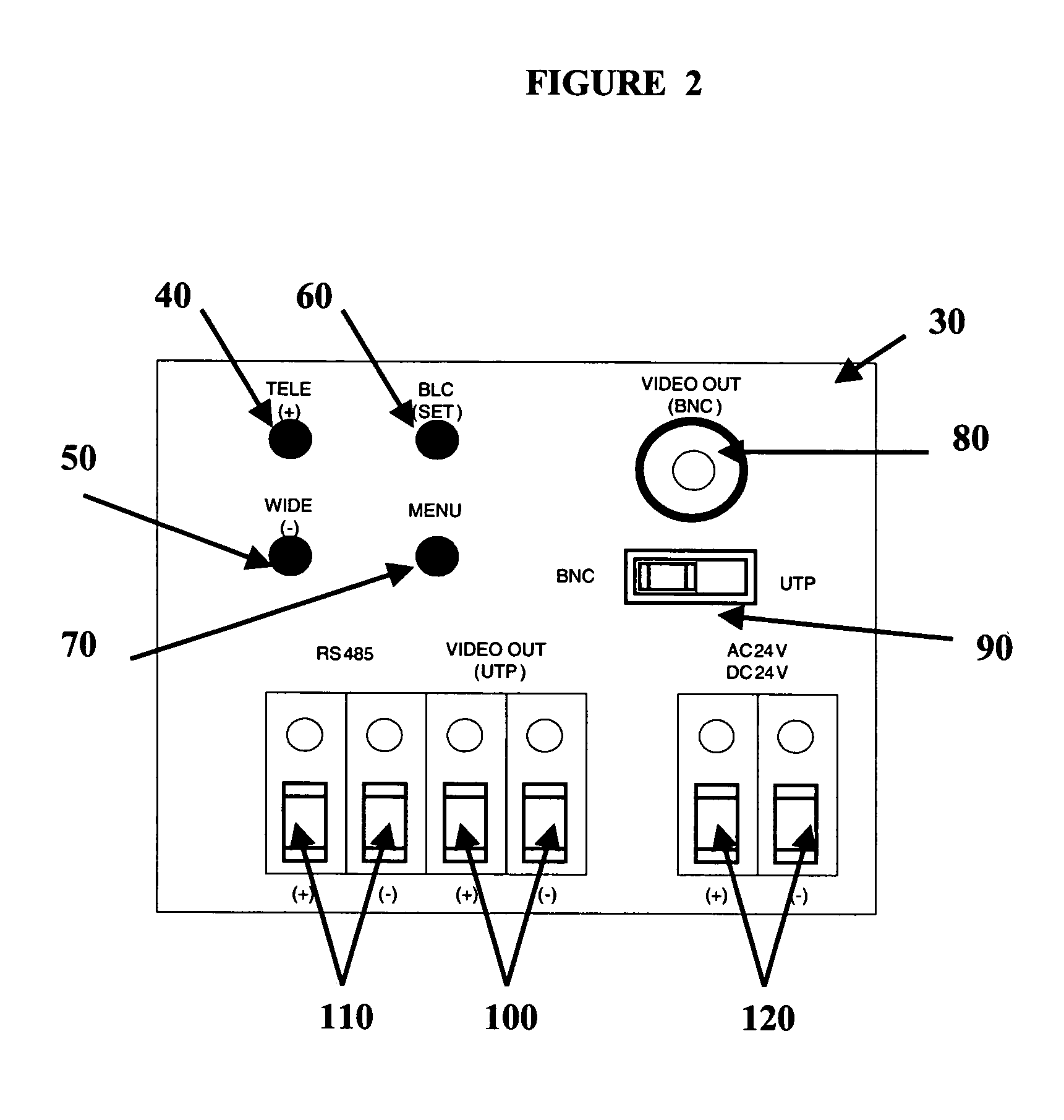
[0019]FIG. 2 is a rear view of a preferred camera system 10 showing a possible set of switches and terminals on a rear panel 30. The top part of the panel contains a number of optional elements. A TELE element 40 provides manual control for increased magnif...


PUM


Abstract

A camera device with unitary interface cabling has a built-in balun for converting unbalanced video signal to balanced video signal for transmission from an on-board twisted pair video output connector, a power connector, a PZT control signal connector, and all said connectors adapted for linking with a category 5 of better network cable.

Description

CROSS-REFERENCE TO RELATED APPLICATION [0001] This application claims the benefit under 35 USC §119(e) of the following patent application, the disclosure of which is hereby incorporated by reference thereto in its entirety: U.S. Ser. No. 60 / 568,678 filed May 7, 2004.TECHNICAL FIELD OF THE INVENTION [0002] This invention is related to the field of video cameras, more specifically to a camera with unitary interface cabling. BACKGROUND OF THE INVENTION [0003] Digital video camera systems have many uses, in particular for surveillance or monitoring purposes. For example, such a camera system can be placed near an automatic teller machine (ATM), a cash register or a point of sales device (POS), or in the proximity of doorways of facilities such as office buildings or factories. Other applications include monitoring the entire duration of a process or operation. [0004] Any unauthorized acts or irregularity may be identified and followed up using the digital images captured with such a ca...

Claims


Application Information

Patent Timeline
IPC IPC(8): H04N5/232H04N7/10H04N7/18
CPCH04N7/108H04N5/23203H04N23/66
Inventor HOANG, JACK
Owner I3 INT INC
Learn More